GEK-45375
Note:
The
impedance values given are those
for
minimum
tap
of
each range, the impedance
for
other
taps
at
pickup
current
(tap
rating)
varies
·inversely, (approximate"ly) as the square
of
the tap
rating.
For
example,
an
IFC77
60Hz
relay with
0.5
- 4.0
amp
range
has
an
impedance
of
2.82
ohms
on
the 0.5
:.mp
tap.
The
impedance
of
the 2.0
amp
tap
·is
(0.5/2.0)2
X 2.82 = 0.176
ohms.
The
Hi-Seismic instantaneous
unit
burdens are l"isted in Table 9.
TABLE
Jl
Hi
Hz
Link
Range
Min
Burdens
at
Min.
Bu.rdens-
ln
Seismic
Inst.
Uni·
_(Amos)
2-50
6-150
2-50
6-150
"---·-
TIME
OVERC.URRENT
UNIT_
Pickup
Position
60
I
H
___
...._
J.__b_
__
60
H
L
50
H
·-·
L
50
H
(Amps)
Pickup
P"ickup
(Ohms)
(Amps)
--·····J•
•
R X ·
I
?-~
?
0.750 0.650
10-50
10
0.070 0.024
6-30
_ 6
___
,_Q_,JlQ
_
0.078
..
30-,.50
30
0.022 0.005
2-10
2
0.625 0.542
10-50
10
0.058 0.020
6-30
6 0.092 0.065
30-150_
30
0.018 0.004
CHARACTERISTJ(}_
Ohms
(Z)
.. -
...
Iime.s..
'i!;]\.yJL.,_
___
z
3_
10
i
20
i
0.992 0.634
0.480 0.457
0.074_
0.072 0.071
0.070
0.1]Ji
~.0~2
. Q
.081
0.079
0.023 0.022
O.Q.s2
0.022
0.827 0.528 0.400
0.380
0.062 0.060
0.059 0.058
o.
112
0.079
0.068 0.066
0.019 0.018
0.018 0.018
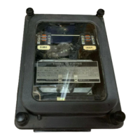
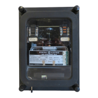
Pickup in these relays
is
defined as the
current
required
to
close the contacts
from
the 0.5 time
dial
position.
Current
settings
are
made
by
means
of
two
movable
leads
which
connect to the tap block
at
the top
of
the support
structure,
see Figure 1.
The
tap block
is
marked
A through
J,
A through M
or
A through
N.
See
the nameplate
on
the
relay
for
tap
settings.
Example:
The
2
amp
tap for a 1
to
12
IFC77
time overcurrent
relay
requires
one
movable
lead in
position
D
and
the
other
in
position
H .
.Qperating
Time
Accur3.£)1_
The
IFC
relays should operate within
±7%
or±
the time dial
setting
times 0.010 seconds, whichever
is
I l
greater,
of
the published time curve. Figures 6-8
and
20-22
show
the various time-current
characteristics
( '
for
the
IFC
relays.
The
setting
of
the time dial determines the length
of
time required to
close
the con-
\,)
tacts
for
a given
current.
The
higher the time dial
setting
the longer the operating time.
The
contacts are
just
closed
when
the time dial
is
set
to zero.
The
maximum
time
setting
occurs
when
the time dial
is
set
to
10
and
the 'disk
has
to
travel
its
maximum
distance to close the
contacts.
Res.tl_
The
unit
resets
at
90%
of
the
m"inimum
closing .current. Reset times are proportionate to the time
di a 1
settings.
The
time to
reset
to the
number
1 O time
di
a 1 pas i
ti
on
when
the current
is
reduced to zero
is
approximately
60
seconds
for
the
1FC53
and
77
relays.
The
IFC51
relay
will
reset
in approximately 7
seconds
from
the
same
number
10
time
dial.
8
g·<~
\;;#
Courtesy of NationalSwitchgear.com
 Loading...