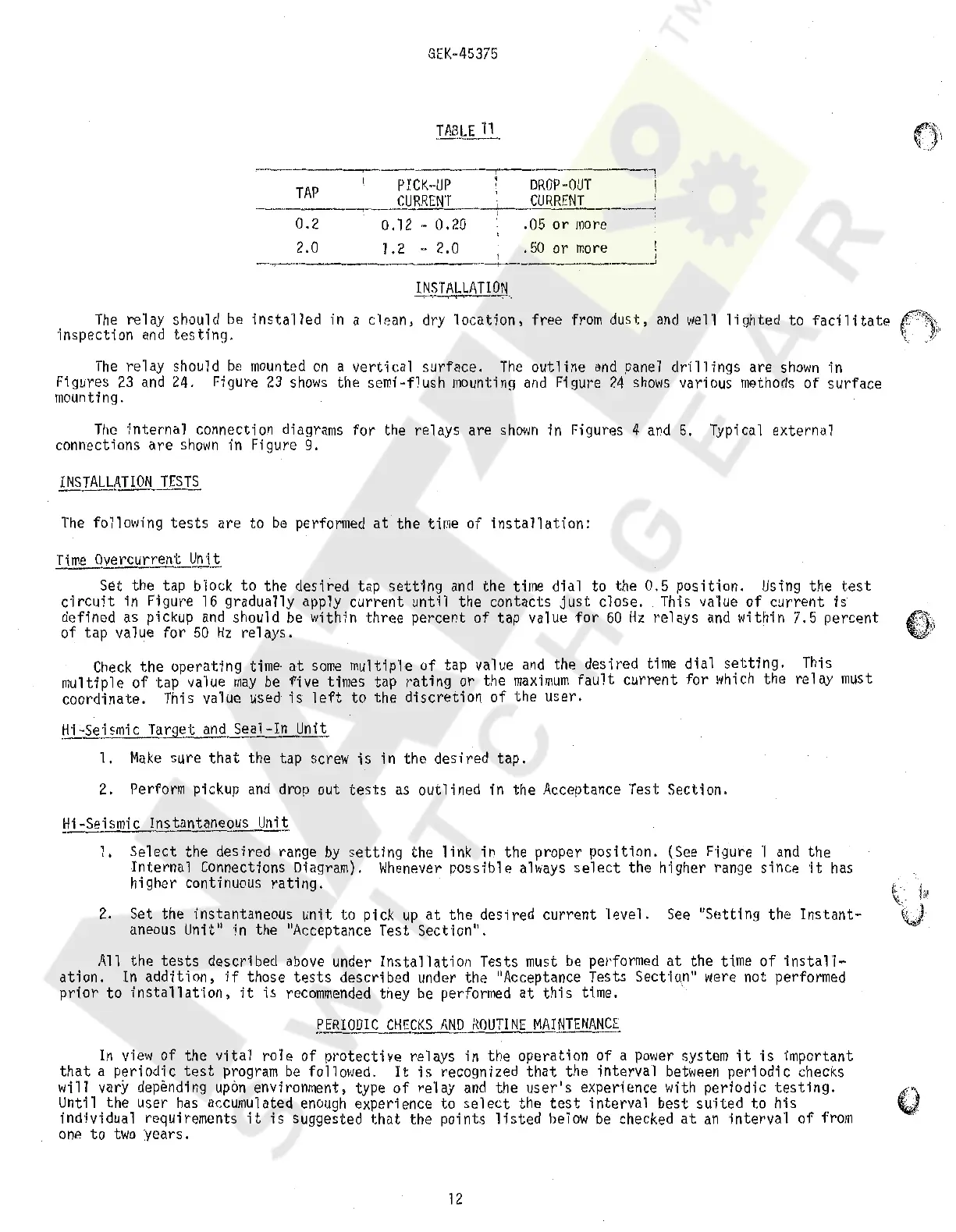
TAP
0.2
GEK-45375
PICK-UP
CURRENT
0.12 - 0.20
DROP-OUT
CURRENT
.05
or
more
2.0 1.2 - 2.0 .50 or
more
I I
--.
-··-------------~
~
INSTALLATION
The
relay should
be
installed
in a clean, dry
location,
free
from
dust,
and
>Jell
lighted
to
facilitate
inspection
and
testing.
The
relay should
be
mounted
on
a
vertical
surface.
The
outline
and
panel
drillfogs
are
shown
in
Figures
23
and
24. Figure
23
shows
the semi-flush mounting
and
Figure
24
shows
various
methods
of
surface
mounting.
The
internal
connection
di
a
grams
for the relays are
shown
in Figures 4
and
5. Typical external
connections
are
shown
in Figure 9.
The
following
tests
are to
be
performed
at
the time of
installation:
Time
Overcurrent Unit
Set the tap block to the desired tap
setting
and
the time dial to the 0.5
position.
Using
the
test
circuit
in Figure
16
gradually apply
current
until the contacts
just
close. This value
of
current
is
defined
as
pickup
and
should
be
within three percent of tap value for
60
Hz
relays
and
within 7.5 percent
of tap value for
50
Hz
relays.
Check
the operating
time·
at
some
multiple of tap value
and
the desired time dial
setting.
multiple of tap value
may
be
five times tap
rating
or the
maximum
fault
current
for
which
the
coordinate. This value used
is
left
to the
discretion
of
the user.
Hi-Se_ismic
Target
and
Seal-In Unit
1.
Make
sure
that
the tap
screw
is
in the desired tap.
2.
Perform pickup
and
drop out
tests
as
outlined in the Acceptance Test Section.
~i-Seismic
Instantaneous
Uni~
This
relay
must
l.
Select the desired range
by
setting
the
link
in the proper posit·ion.
{See
F·igure
·1
and
the
Internal Connections Diagram).
Whenever
possible
always
select
the higher range since ·it
has
higher continuous
rating.
2.
Set the instantaneous unit to pick
up
at
the desired current 'level.
See
"Setting the
Instant-
aneous
Unit" in the "Acceptance Test Section".
All
the
tests
described
above
under
Installation
Tests
must
be
performed
at
the time of
install~
ation.
In
addition,
if
those
tests
described under the "Acceptance Tests Sect'lo.n"
were
not performed
prior
to
installatfon,
it
is
recommended
they
be
performed
at
this
time.
f_ERIODJC
CHE~KS
AND
ROUTINE
MAINTENANCE_
In
view
of the
vital
role
of protective relays in the operation of a
power
system
it
is
important
that
a periodic
test
program
be
followed.
It
is
recognized
that
the interval
between
periodic checks
will vary depending
upon
environment, type
of
re'lay
and
the
user's
experience with periodic
testing.
Until the user
has
accumulated
enough
experience to
select
the
test
interval best
suited
to his
individual requirements
it
is
suggested
that
the points
listed
below
be
checked
at
an
interva'I of
from
one
to
two
:years.
12
IP':!.,;
~-
j''
11"1
v
Courtesy of NationalSwitchgear.com
 Loading...