GEK-45375
Vlhen
setting
these relays
to
coordinate
1;1th
downstream
relays,
a coordination time
of
from
0.25
()
to 0.40 seconds
is
generally allowed,
depend·inq
on
the
clearing
time
of
the breaker invo·lved. These
coordination
t·imes
include, in addition to breaker clear·ing time, 0.10 seconds for relay overtravel
and
0.17 seconds
for
safety
factor.
For
examp"le,
if
the breaker c'learing time
is
0.13 seconds
(8
cycles),
the coordination time
1<ould
be
0.40 seconds (0.13+0.l0+0.17).
If
the relay time
is
set
by
test
at
the
current
level in
question,
the
safety
factor
may
be
reduced to 0.07 seconds.
Then
H the
downstream
breaker time
is
5 cycles (0.08 seconds) a
minimum
of
0.25 seconds (0.08+0.10+0.07) could
be
allowed for coordination.
If
relay coordination times are maroinal
or
impossible to
obtain,
use the
relay overtravel curves
of
Figures 10,
ll
or
12
to
refine
the
relay
settings.
First
determine the relay
operating time necessary to
just
match
the operating time
of
the downstream
relay
with
which
coordination
is
desired. Determine the mu'ltiple
of
pickup
and
the necessary time dial
setting
to provide
this
relay
operating time.
Use
the appropriate curve
of
Figure 10,
11
or
12
to determine the overtravel time in
percent
of
operating
t·ime
and
convert
this
itlto real time.
Add
this
time to the breaker time
and
the
safety
factor
time
and
the
original
relay
operating time to determine the
final
relay
operating time
re-
quired. Set the relay to
this
value.
Once
the
current
in the relay operating coil
is
cut
off
the
relay
contacts
wi"ll
open
in approximately
six cycles
(O. l second) with
normal
adjustment
of
contact wipe. This permits the
use
of the
relay
in
conjunct·ion with instantaneous reclosing
schemes
without
risk
of
a
false
retrip
when
the
circuit
breaker
is
reclosed
on
a
circuit
from
v1hich
a
fault
has
just
been
cleared.
The
instantaneous overcurrent
unit
present in the I
FC51
B,
I
FC53B
and
I
FC77B
re 1
ays
has a trans
·i
ent
overreach
characteristic
as
illustrated
in Figure
13.
This
is
the
result
of
the
DC
offset
that
is
usuall~
present in the
line
current
at
the inception
of
a
fault.
When
determining the pickup
setting
for
this
unit
the
transient
overreach
must
be
taken
into
consideration.
The
percent
transient
overreach
should
be
app"lied to proportionately reduce the
calculated
pickup
setting
so
that
the instantaneous
unit
will not overreach a
downstream
device
and
thereby cause a loss
of
coordination in the system
protection
scheme.
The
operating time
characteristics
of
this
unit
are
sho'-m
in Fioure 14.
CONSTRUCTION
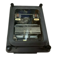
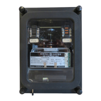
The
IFC
induction disk relays
consist
of
a
molded
case, cover, support
structure
assembly,
and
a
connection plug to
make
up
the
electrical
connection.
See
Cover
Figure
and
Figures 1
,2,3
and
19.
Figures 2
and
3
show
the induction
unit
mounted
to the
molded
support
structure.
This disk
is
activated
by
a
current
operating
coil
mounted
on
either
a laminated
EE
or
U-Magnet.
The
disk
and
shaft
assembly
carries
a
moving
contact
wh·ich"
completes the alarm
or
trip
circuit
·1vhen
it
touches a
stationary
contact.
The
disk assembly
is
restrained
by
a
spiral
spring to give the proper contact closing
current.
Its
rota-
tion
is
retarded
by
a permanent
magnet
mounted
in a
molded
housing
on
the support
structure.
The
drav1out
connect·ion/test system for the
Cl
case,
shown
in Figure 19,
has
provisions for
14
connec-
tion
points,
and
a
visible
CT
shorting
bar located
up
front.
As
th~
connection plug
i~
wi~hdr~vm?
it
clears
the
shorter
contact fingers in the output contact
circuits
f·1rst. Thus, the
trip
c1rcu1t
1s
opened
before
any
other
circuits
are disconnected. Next,
current
circuit
fingers
on
the case connection block
engage the shorting bar (located
at
the lower
front
of
the case) to
short··circuit
external
current
transformer secondary connections.
The
window
provides visual confirmation
of
CT
shorting.
The
connection plug then
clears
the
current
circuit
contact
fingers
on
the case
and
finally
those
on
the
relay
support
structure
to
completely de-energize the drawout element.
There
is
a Hi-Seismic
target
and
seal-in
unit
mounted
on
the
front
to the
left
of
the
shaft
of
the time overcurrent
unit,
see Figure 1.
The
sea·l··in
unit
has
its
coil in
series
and
its
contacts in
parallel
with the contacts of the time overcurrent unit
such
that
when
the induction
unit
contacts
close
the
seal-in
unit
picks
up
and
seals
in.
When
the
seal-in
unit
picks up,
it
raises
a
target
into
view
which
latches
up
and
remains exposed
until
released
by
pressing a
reset
button located
on
the upper
left
side
of
the cover.
The
!FC
"B"
model
re.lays in addition
to
the
above
contain a Hi-Seismic instantaneous un'it, see
Figure 1.
The
instantaneous
unit
is
a small hinged type
unit
which
is
mounted
on
the
front
to
the
right
of
the
shaft
of
the time overcurrent
unit.
Its
contacts are normally connected in
parallel
with the
contacts
of
the time overcurrent
unit
and
its
coil
is
connected in
series
with the time overcurrent
unit.
When
the instantaneous
unit
picks
up
it
raises
a
target
which
latche~
up
~nd
remains exposed
until
it
is
released.
The
same
reset
button
that
releases
the
target
seal-in
urnt
also
releases
the
target
of
the instantaneous un'it.
A maqnetic shie.ld, depicted in Figure
1,
is
mounted
t?
~he
support
structure
of inverse
and
very
inverse time overcurrent
IFC
relays,
to eliminate the proximity
affect
of
external magnetic
materials.
Courtesy of NationalSwitchgear.com
 Loading...