– 18 –
5. Tilt the top of the control panel out, and
mark and disconnect all the wiring harnesses
connected to the smart board.
6. Remove the Phillips-head screw that attaches
the ground wire to the control panel assembly.
Note: Model JVM1540 does not have this ground
wire.
Duct Assembly
To access the cavity TCO, the duct assembly must
be removed.
To remove the duct assembly:
Remove the outer cover. (See 1. Outer Cover.)
Remove the 3 Phillips-head screws that attach 2.
the duct assembly to the oven.
3. Lift the duct assembly up at the rear and pull
towards the back to release the tabs securing it
to the front frame.
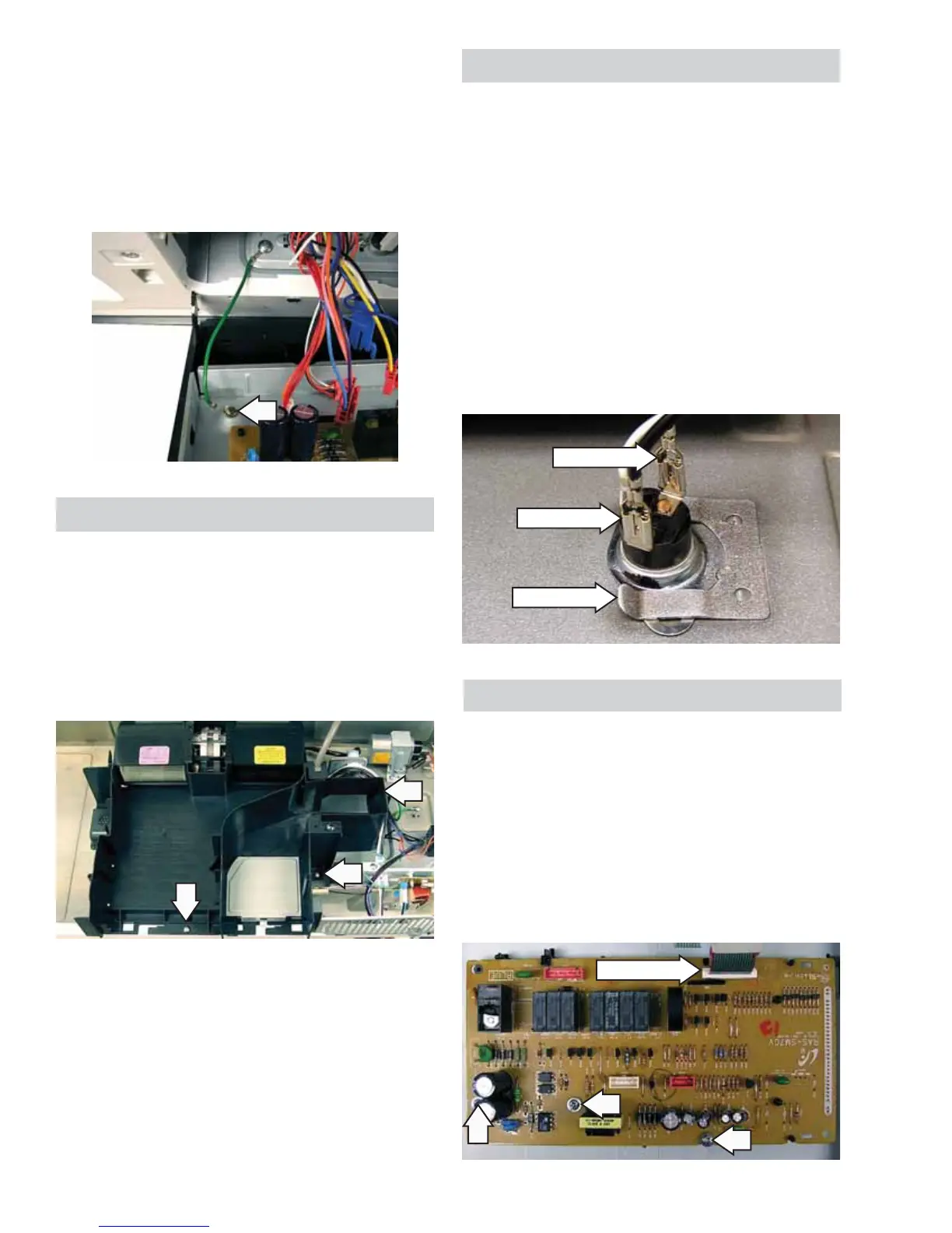
Cavity Thermal Cutout
The cavity thermal cutout is located on the top side
of the oven cavity beside the exhaust duct. The
cutout has a temperature rating of 212˚F.
The cavity TCO is not resettable.
To remove the oven thermal cutout:
Remove the outer cover. (See 1. Outer Cover.)
Remove the duct assembly. (See Du2. ct Assembly.)
Disconnect wiring to the oven thermal cutout.3.
Slide the oven thermal cutout to the left to 4.
remove it from the spring clip attaching it to the
oven cavity.
Disconnect
Disconnect
Spring Clip
Disconnect
Smart Board
To remove the smart board:
Remove the control panel assembly. (See 1. Control
Panel Assembly.)
Disconnect the touch panel ribbon from the 2.
smart board.
Remove the 3 Phillips-head screws that attach 3.
the smart board to the control board frame then
lift the smart board off the frame.
 Loading...