Do you have a question about the GE JVM1750 and is the answer not in the manual?
Instructions for reattaching grounding devices after servicing to ensure safety.
Essential safety measures to prevent microwave energy exposure during repair work.
Explains the coding system used in the microwave oven model numbers for features and specifications.
Details how to decode the serial number to determine the month and year of manufacture.
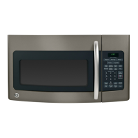
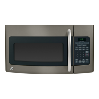
Highlights specific functions like Sensor Cook, Auto/Time Defrost, Turntable On/Off, and Oven Rack.
Details the door handle, latches, and window with metal shield for oven access and viewing.
Covers the touch control panel for operation and the cooktop light for illumination.
Describes the grease filter, removable turntable, and convenience guide features.
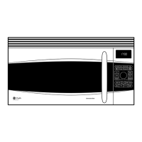
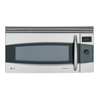
Details the door handle, latches, and window for oven access and viewing.
Covers the touch control panel for operation and the cooktop light for illumination.
Describes the shelf, grease filter, turntable, and rating plate features.
Explains manual time cooking, auto/time defrost, and express cook functions.
Instructions for using the defrost function based on food weight.
Details pre-programmed options like snacks, beverage, reheat, potato, vegetable, and sensor cooking.
Explains manual time cooking, auto/time defrost, and express cook functions.
Details pre-programmed options like snacks, beverage, reheat, potato, and vegetable.
Step-by-step instructions on how to activate and deactivate the demo mode for demonstration purposes.
Explains how functions are displayed and that no components are energized during demo mode.
Illustrates the location of external components like the grill assembly and control panel.
Shows the placement of internal parts such as cooling fan motor, hood TCO, and bottom TCO.
Illustrates the location of internal components from the right side, including magnetron, transformer, and capacitor.
Details the components and connectors on the back and front sides of the JVM1750 smart board.
Lists and explains the purpose of key connectors like CN201, CN202, CN301, CN401, and RY203.
Details the components and connectors on the back and front sides of the JVM1540 smart board.
Lists and explains the purpose of key connectors like CN201, CN202, CN401, and RY203.
Step-by-step instructions for safely removing the entire microwave oven unit from its installation.
Guidance on how to remove the outer metal casing to access internal components.
Instructions for removing the vent blower assembly located at the top rear of the microwave oven.
Steps to remove the grill assembly, applicable to Model JVM1540 and JVM1750.
Guidance on accessing and replacing the interior light bulb.
Steps to remove the control panel assembly, including the smart board and touch pad.
Instructions for removing the duct assembly to gain access to other components like the cavity TCO.
Steps to remove and replace the cavity thermal cutout (TCO) located near the exhaust duct.
Detailed procedure for removing the smart board from its frame.
Procedure for removing the bottom thermal cutout located behind the control panel.
Steps to remove the thermal cutout located on the magnetron.
Guidance on removing the hood thermal cutout attached to the base plate.
Instructions for removing the stirrer assembly located at the top of the oven cavity.
Explains the purpose of the noise filter and how to remove it.
Guidance on checking and replacing the main line fuse.
Procedures for removing the magnetron, including crucial capacitor discharge warnings.
Steps for removing the vent fan motor capacitor located above the cooling fan.
Instructions for removing the cooling fan and motor assembly from the right side.
Detailed steps for removing the high voltage capacitor and diode, including safety warnings.
Procedure for removing the high voltage transformer, emphasizing capacitor discharge safety.
Explains the design and function of the primary, door sensing, and monitor interlock switches.
Procedures and continuity checks for the primary interlock and door sensing switches when the door is opened or closed.
Steps to test the monitor switch, including its operation by the latch pawl and continuity checks.
Instructions for removing the turntable motor located at the bottom of the oven.
Guidance on how to access and replace the oven's surface lamp bulbs.
Notes that the door is available as a complete assembly or individual parts.
A step-by-step guide to diagnose issues with the JVM1750 microwave oven.
Explains the meaning of symbols, abbreviations, and legends used in the diagnostic flow chart.
A step-by-step guide to diagnose issues with the JVM1540 microwave oven.
Explains the meaning of symbols, abbreviations, and legends used in the diagnostic flow chart.
Explains the design and function of the primary, door sensing, and monitor interlock switches.
Procedures and continuity checks for the primary interlock and door sensing switches when the door is opened or closed.
Steps to test the monitor switch, including its operation by the latch pawl and continuity checks.
Details the ribbon connections for testing key panel pads on JVM1750 models.
Details the ribbon connections for testing key panel pads on JVM1540 models.
Presents the electrical schematic diagram for the JVM1750 microwave oven.
Explains the color coding and symbols used in the schematic and wiring diagrams.
Illustrates the internal wiring connections specific to the JVM1750 microwave oven.
Explains the color coding and symbols used in the JVM1750 schematic and wiring diagrams.
Presents the electrical schematic diagram for the JVM1540 microwave oven.
Explains the color coding and symbols used in the JVM1540 schematic and wiring diagrams.
Illustrates the internal wiring connections specific to the JVM1540 microwave oven.
Explains the color coding and symbols used in the JVM1540 schematic and wiring diagrams.
Outlines GE's policy for replacing parts or the entire microwave oven within one year of purchase.
Lists conditions and damages that are not covered under the product warranty.
Explains limitations on implied warranties and consumer legal rights.
| Brand | GE |
|---|---|
| Model | JVM1750 |
| Category | Microwave Oven |
| Language | English |