GEK-113285A G650 Generator Protection & Control System 5-53
5 SETTINGS 5.4 PROTECTION ELEMENTS
5
5.4.5.2 GROUND INSTANTANEOUS OVERCURRENT ELEMENT (50G)
Ground IOC is a ground instantaneous overcurrent protection element, with a setting range from 0.05 A to 160 A, which can
also be time delayed. The delay is selectable between 0.00 and 900 seconds. The ground current input quantity is
measured from the ground input, and it may be programmed as Fundamental phasor magnitude or RMS magnitude as
required by the application. The element incorporates a reset time selectable between 0 and 900 seconds, and a block
input that resets the pickup and trip signals to 0. The element outputs are the general pickup and trip signals of the element.
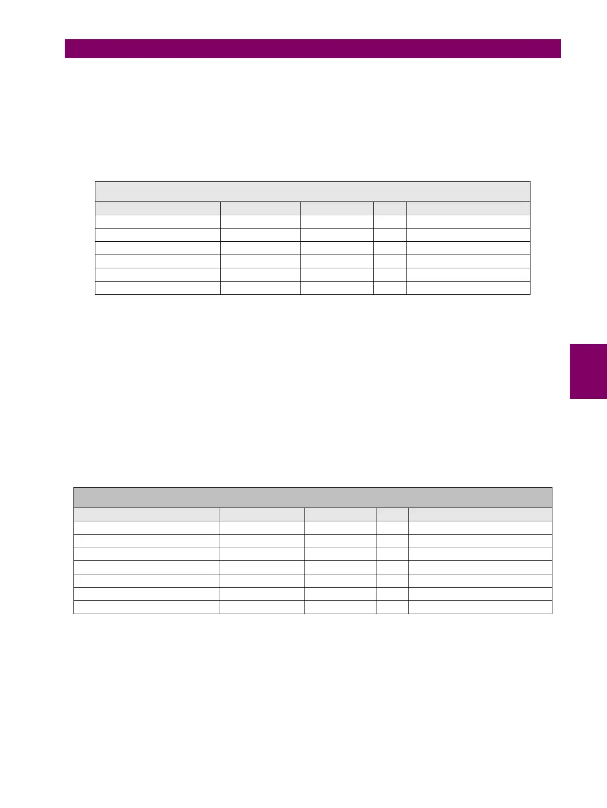
Table 5–49: 50G ELEMENT SETTINGS
The snapshot event setting enables or disables the snapshot event generation for this element.
5.4.5.3 GROUND DIRECTIONAL ELEMENT (67G)
Ground directional is a directional protection element, used for monitoring the ground overcurrent elements. The operation
magnitude is the ground current measured directly from the corresponding input (B9-B10), while the polarization magnitude
is the neutral voltage (V
n
). The neutral voltage is calculated from the three phase voltages ( when VG or VX is selected as
Auxiliary Voltage setting in the General Settings main menu) or measured from the dedicated voltage input (A11-A12)when
VN is selected as Auxiliary Voltage setting in the General Settings main menu.
In case of using the voltage measured from the dedicated voltage input terminals, the Auxiliary Voltage setting in General
settings must be V
N.
As in the case of a phase directional element, this element incorporates a voltage loss logic that allows blocking or
permitting the trip by means of a setting.
Table 5–50: 67G ELEMENT SETTINGS
Operation of the Ground directional element 67G is similar to the operation of the neutral directional element 67N (refer to
section 5.4.4.3), with the exception that the operation magnitude here is the ground current Ig (67G), measured from the
input terminals B9-B10 instead of the Neutral current, In (67N), calculated from the phase currents.
Polarization magnitudes can be, as in the case of 67N, Polarization voltage (3Vo), either calculated from the phase
voltages or measured from terminals A11-A12 when VN is selected as Auxiliary Voltage setting in the General Settings
main menu, or polarization current (Ip), measured from the fifth input transformer terminals, Isg, terminals B11-B12.
The following table shows the used magnitudes in each of the Polarization possibilities:
SETPOINT > PROTECTION ELEMENTS > GROUND CURRENT > GROUND IOC
GROUND IOC 1> GROUND IOC 2 > GROUND IOC 3
SETTING DESCRIPTION NAME DEFAULT VALUE STEP RANGE
Function permission Function DISABLED N/A [DISABLED – ENABLED]
Input type Input PHASOR(DFT) N/A [PHASOR – RMS]
Pickup level Pickup Level 30.00 0.01 A [0.05 : 160.00]
Trip time Trip Delay 0.00 0.01 s [0.00 : 900.00]
Reset time Reset Delay 0.00 0.01 s [0.00 : 900.00]
Snapshot event generation Snapshot Events ENABLED N/A [DISABLED – ENABLED]
SETPOINT > PROTECTION ELEMENTS > GROUND CURRENT > GROUND DIRECTIONAL >
GROUND DIRECTIONAL 1> GROUND DIRECTIONAL 2 > GROUND DIRECTIONAL 3
SETTING DESCRIPTION NAME DEFAULT VALUE STEP RANGE
Function permission Function DISABLED N/A [DISABLED – ENABLED]
Maximum Torque Angle MTA -45 1 Deg [-90 : +90]
Operation Direction Direction FORWARD N/A [FORWARD – REVERSE]
Polarization type Polarization VO N/A [V
0
– I
P
– V
0
+I
P
– V
0
*I
P
]
Block logic type Block Logic PERMISSION N/A [BLOCK – PERMISSION]
Polarization voltage threshold Pol V Threshold 0 1 V [0 : 00]
Snapshot event generation Snapshot Events ENABLED N/A [DISABLED – ENABLED]


 To Next Page