5-58 G650 Generator Protection & Control System GEK-113285A
5.4 PROTECTION ELEMENTS 5 SETTINGS
Table 5–58: RESTRICTED GROUND FAULT INTERNAL STATES
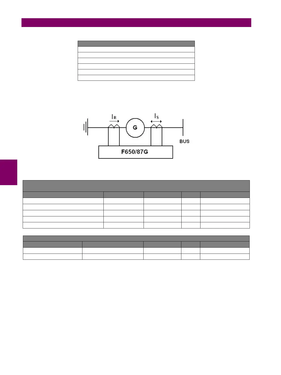
5.4.6.1 RESTRICTED GROUND FAULT SETTINGS EXAMPLE
The example does not apply any slope, it is only intended to explain the pickup setting selection when the CT ratios are
different for phases and ground.
• If the Phase CT Transformers are 400/5 this means a Phase CT Ratio of 80
• If the Ground CT Transformer is 200/5 this means a Ground CT Ratio of 40
Sensitivity is given in primary amperes with Phase CT Ratio reference, this is:
Sens =[Ground Fault Pickup] x [Phase CT Ratio]
If the Ground Fault Pickup setting is 0.3 A. This setting means that for phases the unit will trip when the Igd with phase
current reference is higher that 24 A, and with ground current reference is higher than 12 A.
RESTRICTED GROUND FAULT INTERNAL STATES
RESTR GND FLT1 PKP
RESTR GND FLT1 OP
RESTR GND FLT2 PKP
RESTR GND FLT2 OP
RESTR GND FLT3 PKP
RESTR GND FLT3 OP
SETPOINT > PROTECTION ELEMENTS > GROUND CURRENT > RESTRICTED GND FAULT >
RESTRICTED GND FAULT 1> RESTRICTED GND FAULT 2 > RESTRICTED GND FAULT 3
SETTING DESCRIPTION NAME DEFAULT VALUE STEP RANGE
Restricted Ground Fault Function permission Function DISABLED N/A [DISABLED – ENABLED]
Restricted Ground Fault Pickup Ground Fault Pickup 0.30 0.01 CT [0.02 : 20.00]
Restricted Ground Fault Slope Ground Fault Slope 0.00 0.01 % [0.00 : 100.00]
Restricted Ground Fault Delay Ground Fault Delay 0.10 0.01 s [0.00 : 600.00]
Snapshot Event generation Snapshot Events ENABLED N/A [DISABLED – ENABLED]
SETPOINT > SYSTEM SETUP > GENERAL SETTINGS
SETTING DESCRIPTION NAME DEFAULT VALUE STEP RANGE
Phase CT Ratio Phase CT Ratio 80.0 0.1 [1.0 : 6000.0]
Ground CT ratio Ground CT Ratio 40.0 0.1 [1.0 : 6000.0]