5-62 G650 Generator Protection & Control System GEK-113285A
5.4 PROTECTION ELEMENTS 5 SETTINGS
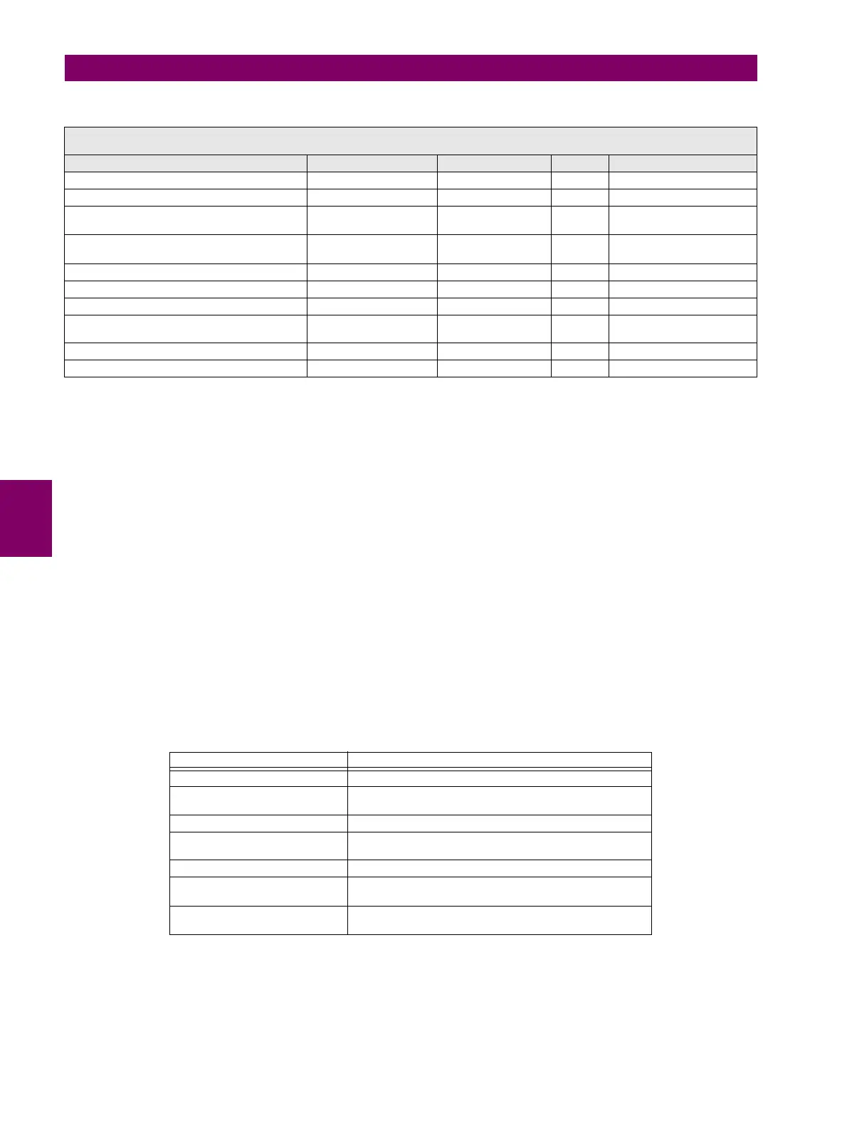
Table 5–63: GENERATOR UNBALANCE ELEMENT SETTINGS
• Gen Unbal Function: This setting allows enabling or disabling the element.
• Gen Unbal Inom: This setting is the rated full load current of the machine.
• Gen Unbal Stg1 Pkp: This setting defines the pickup of the stage 1 element expressed as a percentage of the
nominal current as specified by GEN UNBAL INOM setting. It is typically set at the maximum continuous negative
sequence current rating of the machine.
• Gen Unbal Stg1 K: This setting is the negative sequence capability constant. This value is normally provided by the
generator manufacturer.
• Gen Unbal Stg1 Tmin: This is the minimum operate time of the element.
• Gen Unbal Stg1 Tmax: This is the maximum operate time of the element. This setting can be applied to limit the
maximum tripping time.
• Gen Unbal Stg1 K-Rst: This setting defines the linear reset rate of the stage. This feature provides a thermal memory
of previous unbalance conditions.
• Gen Unbal Stg2 Pkp: This setting defines the pickup of the stage 2 element expressed as a percentage of the
nominal current as specified by GEN UNBAL INOM setting.
• Gen Unbal Stg2 Delay: This is the minimum operate time of the stage 2 element.
Table 5–64: GENERATOR UNBALANCE INTERNAL SIGNALS
SETPOINT > PROTECTION ELEMENTS > NEGATIVE SEQUENCE CURRENT > GENERATOR UNBALANCE >
GENERATOR UNBALANCE 1> GENERATOR UNBALANCE 2 > GENERATOR UNBALANCE 3
SETTING DESCRIPTION NAME DEFAULT VALUE STEP RANGE
Function Permision Function DISABLED N/A [DISABLED – ENABLED]
Generator Rated Full Load Current Gen Unbal Inom 5.00 0.01 A [0.00 : 10.00]
Pickup level for stage 1 (as a percentage of
Gen Unbal Inom)
Gen Unbal Stg1 Pkp 8.00 0.01 % [0.00 : 100.00]
K (Negative sequence capability constant) for
stage 1
Gen Unbal Stg1 K 1.00 0.01 [0.00 : 100.00]
Minimum Operating time for stage 1 Gen Unbal Stg1 Tmin 0.3 0.1 s [0.0 : 1000.0]
Maximum Operating time for stage 1 Gen Unbal Stg1 Tmax 600.0 0.1 s [0.0 : 1000.0]
K for Linear reset of the stage Gen Unbal Stg1 K-Rst 240.0 0.1 [0.0 : 1000.0]
Pickup level for stage 2 (as a percentage of
Gen Unbal Inom)
Gen Unbal Stg2 Pkp 3.00 0.01 % [0.00 : 100.00]
Trip time for stage 2 Gen Unbal Stg2 Delay 5.0 0.1s [0.0 : 1000.0]
Snapshot Event generation Snapshot Events ENABLED N/A [DISABLED – ENABLED]
SIGNAL COMMENT
GEN UNBAL (1, 2, 3) BLOCK Input used to block the element (1, 2, 3) externally
GEN UNBAL (1, 2, 3) STG1 PKP Output used to indicate I2/Inom ratio above stage 1 setting
in units (1, 2, 3)
GEN UNBAL (1, 2, 3) STG1 OP Output used to indicate stage 1 operation in units (1, 2, 3)
GEN UNBAL (1, 2, 3) STG2 PKP Output used to indicate I2/Inom ratio above stage 2 setting
in units (1, 2, 3)
GEN UNBAL (1, 2, 3) STG2 OP Output used to indicate stage 2 operation in units (1, 2, 3)
GEN UNBAL1 PKP This status is a logic OR between the GEN UNBAL(1, 2, 3)
STG1 PKP and GEN UNBAL(1, 2, 3) STG2 PKP
GEN UNBAL1 OP This status is a logic OR between the GEN UNBAL(1, 2, 3)
STG1 OP and GEN UNBAL(1, 2, 3) STG2 OP


 To Next Page