5-136 G650 Generator Protection & Control System GEK-113285A
5.8 RELAY CONFIGURATION 5 SETTINGS
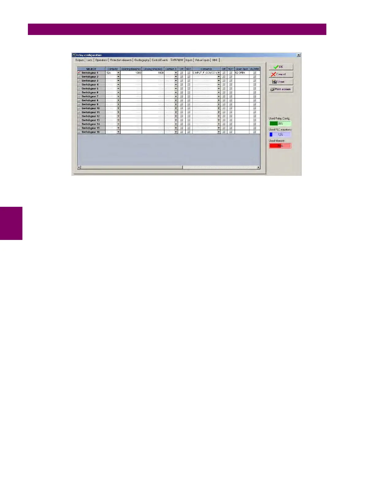
Figure 5–46: SWITCHGEAR CONFIGURATION
Note: when a switchgear device is only monitored (open init and closing init signals are not used), it is not possible to
distinguish between the fail to open or fail to close time, the time used to give an error 00 or 11 signal is the maximum of the
opening and closing time configured for that switchgear.


 To Next Page