HARDWARE
3.1.6. REAR DESCRIPTION
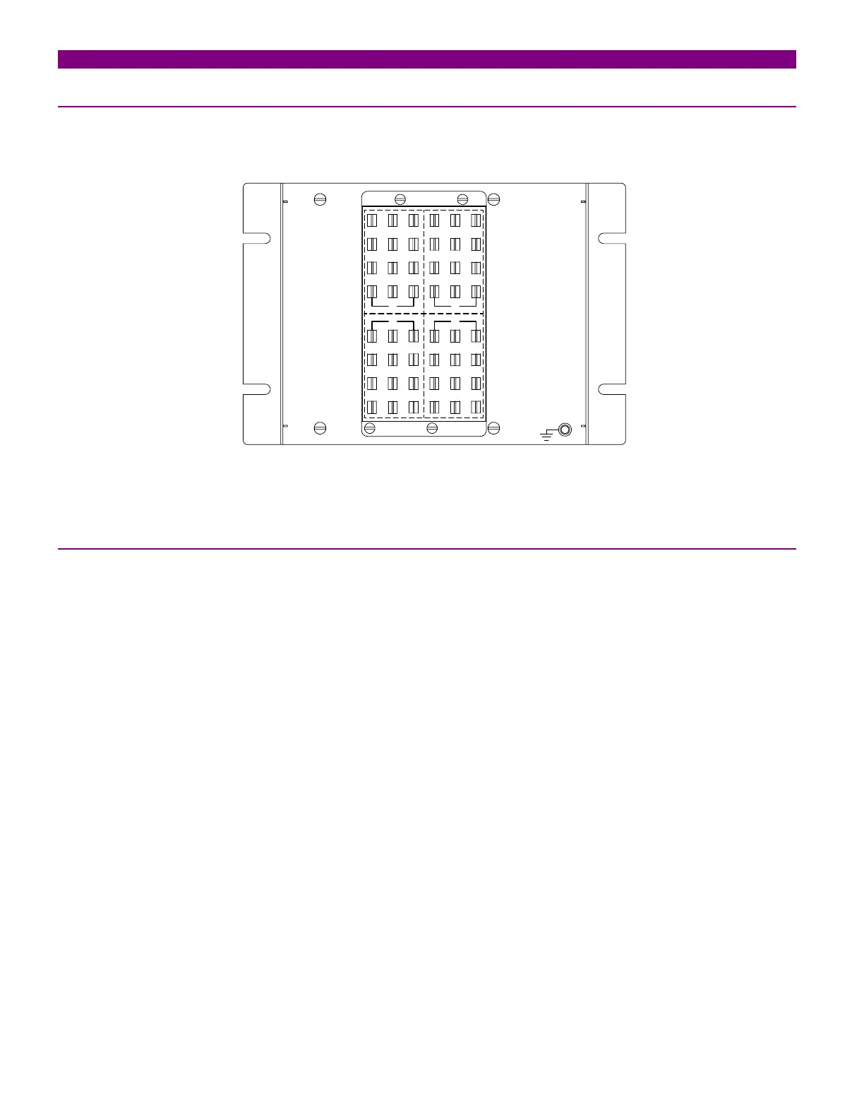
The module is wired through the terminal blocks located at the rear of the unit. The maximum recommended cable
section for this terminal board, with the appropriate terminal, is 6 mm2 (AWG 10).
159
26
10
37
11
4812
159
26
10
37
11
48
12
1
59
2
610
3
711
4
8
12
159
26
10
3711
48
12
A B
CD
FIGURE 3-3 REAR TERMINALS DIAGRAM
3.1.7. INPUTS
HID inputs are composed of three elements:
• Stabilizing resistor
• MOV
• Contact from latching relay
Inputs vary depending on the HID model chosen. Thus, if the model corresponds to a type 1 application in the model
selection list, HID will have one single input; two for a type 2 application and three for a type 3 application.
HIDs can be supplied with or without latching relay.
If the unit includes a latching relay, then MOVs and resistors are dimensioned according to the HLB tripping time,
whereas if the unit does not include a latching relay, resistor and varistors are able to support a tripping time of
250ms.
3-4 HID High Impedance Differential Module GEK-113064