6 NX-
VI. TERMINAL DESCRIPTIONS
Table VI:1
Terminal
Description
DATA
Connect to the NX-8 / NX-8E / NX-8-CF control panel Data terminal. This terminal is the
incoming data-signaling terminal to the
ower su
l
module. The maximum total wire run
from the control panel to all devices, including the NX-320E is 2500 feet.
COM
Connect to the NX-8 / NX-8E / NX-8-CF control panel COMMON terminal. This terminal
supplies the common side of the power to the NX-320E board.
POS
Connect to control panel AUX POWER + terminal. This terminal supplies power to the NX-
320E board.
DATA
This terminal is the outgoing data-signaling terminal for buss extension. The maximum total
wire run from the NX-320E to all outgoing devices is 2500 feet.
COM
Common terminal for any device powered from the NX-320E.
OUT A
Programmable output current limited to 1.9 Amps.
OUT B
Programmable output current limited to 1.9 Amps.
COM
Common terminal for any device powered from the NX-320E.
OUT C
Programmable output current limited to 1.9 Amps.
BELL +
Positive of bell output current limited to 2.5 Amps, but 600mA
for UL applications. Connect as in diagram on page 7.
BELL -
Negative of bell output current limited to 2.5 Amps, but 600mA
for UL applications. Connect as in diagram on page 7.
The total current of the
NX-320E is 2.5 Amps.
TAM
This is an o
tional tam
er terminal. To use this feature, connect the normall
closed tam
er
switch between this terminal and COM. If switch 4 is off, this feature is not used.
EARTH
Earth Ground.
AC
AC Input. Connect to a 16.5V 50 VA Class II UL approved transformer.
AC
AC Input. Connect to a 16.5V 50 VA Class II UL approved transformer.
Total of 1.9 Amps between outputs A,B,C.
Total of 2.5 Amps between Bell and outputs.
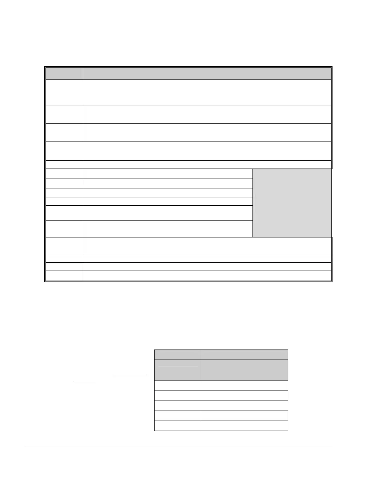
VII. WIRING REQUIREMENTS
Table VII:1
LENGTH WIRE GAUGE
(IN FEET)
WHEN CONNECTED
TO NX-8 / NX-8E / NX-8-CF
400 24
500 24
1000 24
2000 22
For UL COMMERCIAL FIRE
installations, a minimum of
18 AWG shall be used for all
field-wiring applications,
regardless of this chart.
2500 20

 Loading...