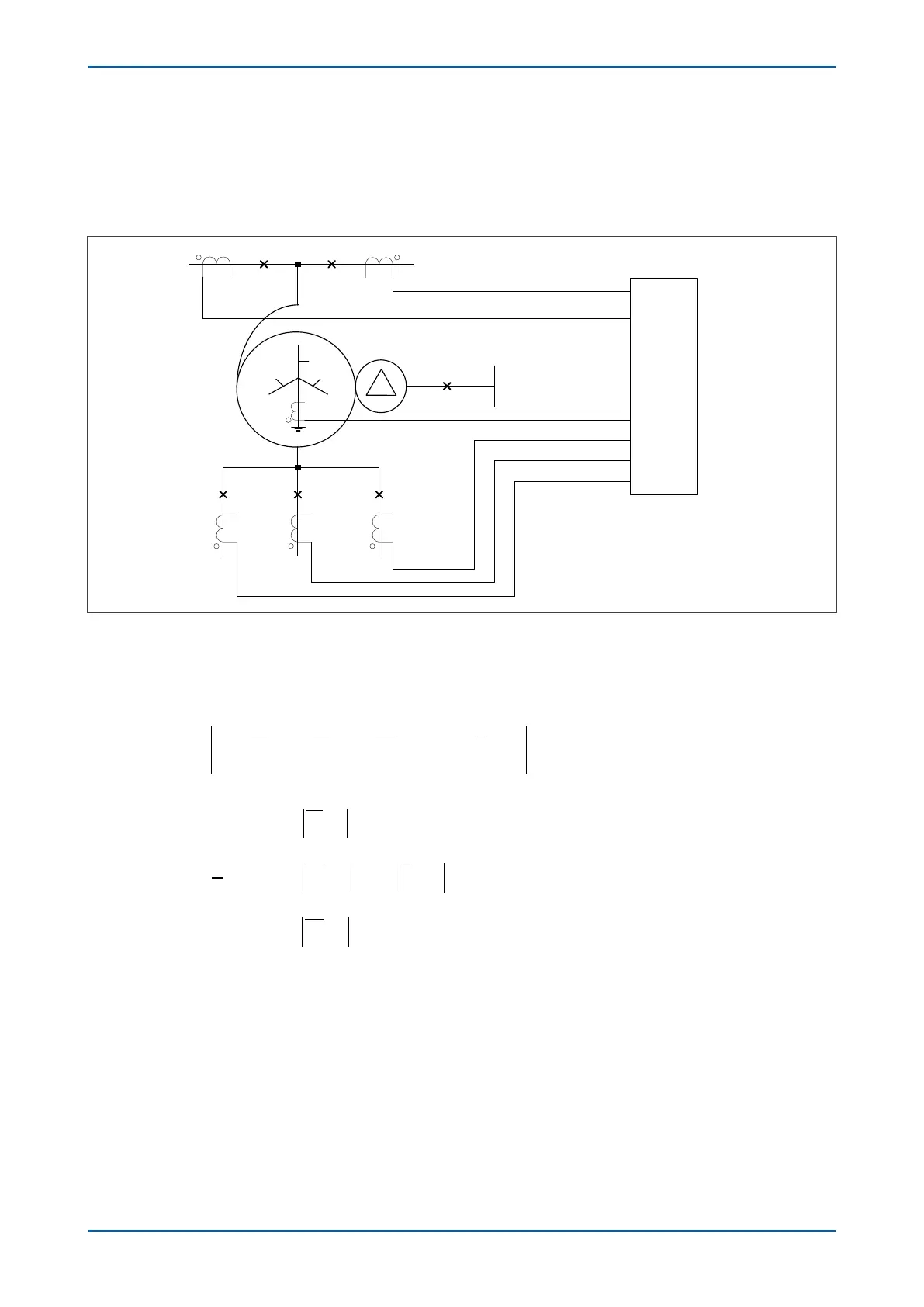
5.2.5 DUAL CB APPLICATION WITH SAME PHASE CT RATIOS
The following diagram shows the situation where low impedance REF is being used in a dual breaker (breaker-and-
a-half
) application where the phase CT ratios are identical. In this example, one phase of an autotransformer is
shown, but the explanation is also applicable to conventional transformers.
T1 CT
TN1 CT
T2 CT
Low
Impedance
REF
V00707
T3 CT T4 CT T5 CT
Figure 85: Low-Z REF for dual CB application with same phase CT ratios
The low impedance REF f
unction can be used in dual breaker (breaker-and-a-half) applications. The line CT ratios
may be identical. In this case the Restricted Earth Fault (REF) Low Impedance (Z) Differential and Bias current
formulae are calculated as follows:
I IA IB IC K I
diff REF
TxCT TxCT
TxCT
n
n
n( )
= + +
( )
+
=
∑
1
TN1 CT
I
IA
IB
IC
bias REF
n
n
n
n
n
n
TxCT
TxCT
TxCT
( )
max=
=
=
=
∑
∑
∑
1
2
1
1
1
+
K I
n
TN1 CT
where:
● Tx CT = T1, T2, T3, T4 or T5.
● Kn = TN1 CT Ratio/ Tx CT Ratio
● TN1 CT Ratio = Neutral CT Ratio.
● Reference: Tx CT.
5.2.6 CT REQUIREMENTS - LOW IMPEDANCE REF
We strongly recommend Class X or Class 5P current transformers for this application.
P64x Chapter 8 - Restricted Earth Fault Protection
P64x-TM-EN-1.3 181