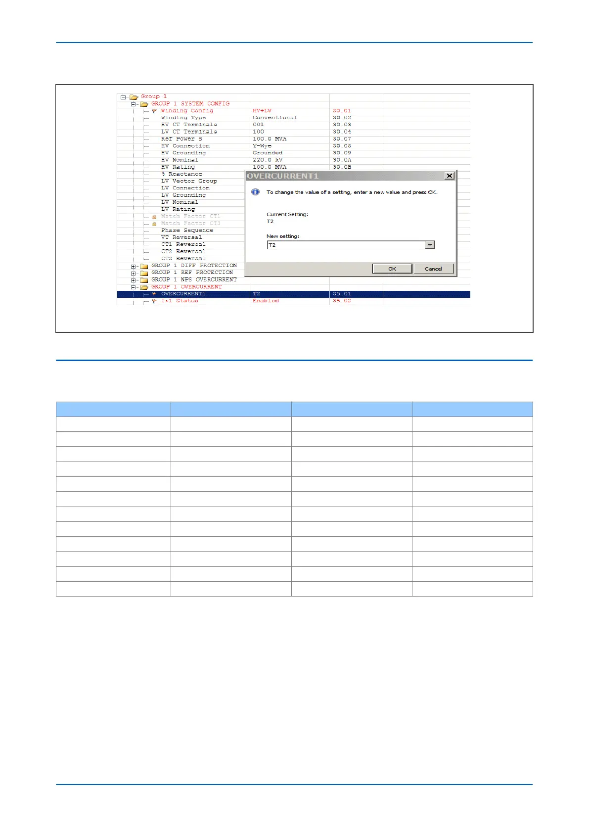
Figure 59: P643 Using spare CT input for overcurrent protection
5.8 SETTING GUIDELINES FOR REFERENCE VECTOR GROUP
The following table shows how to set the zero sequence filter for the different Ref Vector Group options.
Ref Vector Group Zero seq filt HV setting Zero seq filt LV setting Zero seq filt TV setting
0 Enabled Disabled Disabled
1 Disabled Disabled Enabled
2 Enabled Enabled Disabled
3 Disabled Disabled Enabled
4 Enabled Disabled Disabled
5 Disabled Disabled Enabled
6 Enabled Disabled Disabled
7 Disabled Disabled Enabled
8 Enabled Disabled Disabled
9 Disabled Disabled Enabled
10 Enabled Disabled Disabled
11 Disabled Disabled Enabled
In the majority of applications, the reference vector group setting R
ef Vector Group is set to 0. However there are
occasional applications where it may be desirable to set it to a value other than 0.
One example is to increase the sensitivity for phase-to-phase faults where it is used to protect a YNyn0
transformer. In this scenario, the P64x would normally apply a -30° phase shift to both HV and LV windings due to
the way it works. However, by setting the reference vector group to 1, the device knows it does not have to apply a
-30° shift in its calculations, thus increasing its sensitivity to phase-to-phase faults.
Chapter 6 - Transformer Differential Protection P64x
136 P64x-TM-EN-1.3