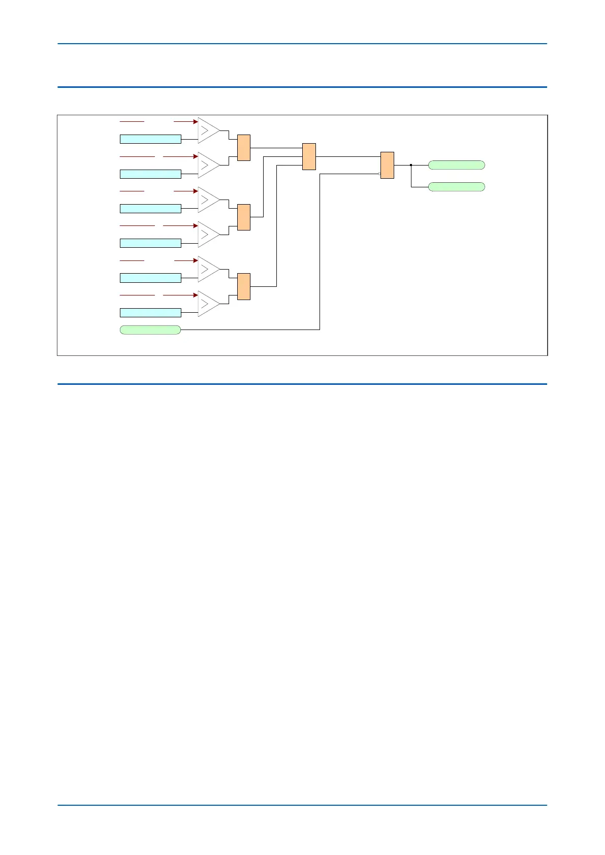
4.2 THROUGH FAULT MONITORING LOGIC
V03201
TF I> Trigger
IA magnitude
TF I2t> Alarm
IA
2
t
&
1
TF I> Trigger
IB magnitude
TF I2t> Alarm
IB
2
t
&
TF I> Trigger
IC magnitude
TF I2t> Alarm
IC
2
t
&
Any Diff Start
Throu fault Alm
TF Recorder trig
&
Figure 63: Through-fault alarm logic
4.3 APPLICATION NOTES
4.3.1 TFM SETTING GUIDELINES
According to IEEE Std. C57.109-1993, values of 3.5 x normal base current may result from overloads rather than
faults. Accor
ding to IEEE C57.91-1995, the suggested load limits depend on the type of transformer and are as
follows:
● For distribution transformers: Loads above the nameplate specification with 65°C rise is 300% of rated load
during short-time loading (0.5 hours or less).
For power transformers: Loads above the nameplate specification with 55°C rise is 200% of rated load.
To set TF I2t> Alarm you should consider the recommendations given in IEEE Std. C57.109-1993 for transformers
built from the early 1970s onwards. For transformers built before this time, always consult the transformer
manufacturer concerning the short circuit withstand capabilities.
Example
The through fault monitoring element can monitor either the HV, the LV or the TV winding. In three winding
applications, you should monitor the winding through which the highest current would flow during an external
fault. Fault studies are required to determine the maximum through fault current and which winding carries the
most current. For example, consider the following autotransformer:
P64x Chapter 7 - Transformer Condition Monitoring
P64x-TM-EN-1.3 155