– 38 –
Evaporator Thermistor
The evaporator thermistor is clipped to the suction
tube line of the evaporator. See Evaporator for
accessing instructions.
Evaporator Thermistor
Replacement
Should a thermistor require replacement, use
plastic bell connectors (part # WR01X10466). Fill
each connector with RTV102 silicone then splice a
new thermistor into the harness as shown in the
illustration.
RTV102
The evaporator fan is the same fan used on previous
models; however, a signifi cant difference is that the
main control board neither requires nor receives
input from the fan feedback/rpm (blue) wire. The fan
utilizes a permanent magnet, 4-pole, DC motor that
operates at three different speeds: high, medium,
and low.
The speed of the fan is controlled by the voltage
output from the main control board. Voltage output
from the main control board to the fan is 13.6 VDC;
however, to regulate the speed of the fan, the main
control board uses pulse width modulation (PWM).
When operating, voltage is sent in pulses (much like
a duty cycle) as opposed to an uninterrupted fl ow.
This pulsing of 13.6 VDC produces effective voltage
being received at the motor, which is equivalent to a
reduction in voltage.
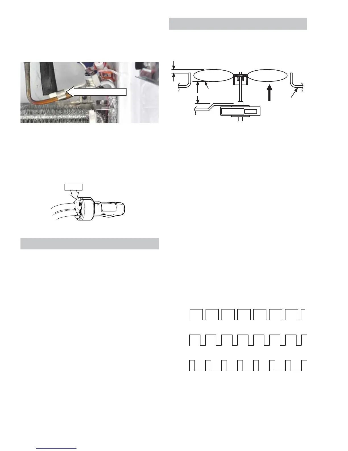
Evaporator Fan
The position of the fan blade in relation to the
shroud is important.
5/16" ± 0.03
Blade tip
1.0" ± 0.05 Target
Motor
Air Flow
Orifice
High Speed (9.5 VDC measured)
Medium Speed (8 VDC measured)
Low Speed (6.5 VDC measured)
9.5 VDC
8 VDC
6.5 VDC
13.6 VDC
0 VDC
0 VDC
0 VDC
13.6 VDC
13.6 VDC
(Continued next page)
Fresh Food and Freezer Light Thermostats
The fresh food and the freezer light thermostats
interrupt power to the lights when the thermostat
temperature reaches 175°F. Power is restored when
the thermostat temperature cools to 155°F.
Each thermostat is attached to the back of each
light housing with an 11/32-in. nut.
To access each thermostat, remove the light cover
and light housing. The fresh food light housing is
held in place by 3 Phillips-head screws. The freezer
light housing is held in place by a single Phillips-
head screw.
Note: It is necessary to remove the freezer light bulb
to access the freezer light housing screw.
Replacement
Should a thermostat require replacement, use
plastic bell connectors (part # WR01X10466). Fill
each connector with RTV102 silicone then splice a
new thermostat into the harness.
 Loading...