– 43 –
• 3°F to 5°F above refrigerator set point - medium
speed.
• 5.5°F to 7°F above refrigerator set point - high
speed.
Note: The compressor will run at medium speed if
the freezer temperature is 20°F or more above the
setpoint.
The use of 3-phase power eliminates the need for
the relay, capacitor, and individual start and run
windings; therefore, the start, run, and common
pins found on conventional compressors are not
applicable on this 3-phase model. Compressor pin
functions are identical and compressor lead wire
confi guration is of no importance. A resistance of
9 Ω to 11 Ω should be read between any 2 of the
3 pins. Should an open occur in the compressor
winding or should one of the compressor lead wires
become open or disconnected, the inverter will stop
voltage output to the compressor.
High compressor torque enables the compressor
to start against high pressure in the sealed system.
When power has been disconnected from an
operating unit, the high torque will enable the
compressor to start immediately upon power
restoration.
Compressor operation is extremely smooth and
cool. The compressor exterior may be slightly higher
than room temperature while operating; therefore, it
may be diffi cult to detect a running unit.
To verify that the compressor is running:
Disconnect power from the unit and place a hand
on the compressor. Reconnect power and feel for
a vibration when the compressor tries to start. It
may take up to 8 seconds before the compressor
attempts to start.
Note:
When ordering a replacement compressor, order •
both the compressor and inverter. Replace
the compressor fi rst. If, after compressor
installation, the compressor fails to start,
replace the inverter.
When servicing the compressor, it is important •
to dress the wiring to keep low voltage DC wiring
and 120 VAC wiring separate.
Evaporator
The following components must be removed in the
appropriate order to access the evaporator:
Unplug the refrigerator.1.
Pull out and remove the ice bin and shelf. 2.
Remove the freezer shelves and baskets. (See 3.
Freezer Shelves and Baskets.)
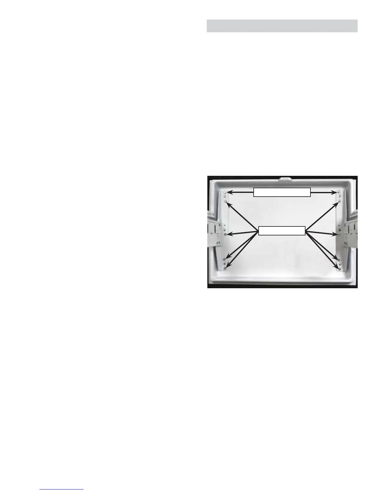
Loosen the top two 4.
3
/
8
-in. hex-head screws 1
full turn, then remove the remaining eight
3
/
8
-in.
hex-head screws that attach the drawer front to
the rail assemblies.
Note: Do not remove the torx screws from the rail
assemblies.
Lift and remove the drawer front and place it on 5.
a protected surface.
Note: To ensure correct alignment when installing
the drawer front, place the top two
3
/
8
-in. hex-
head screws into the open slots on top of each rail
assembly, then install the center screws.
Install the remaining six
3
/
8
-in. hex-head screws, then
tighten all screws fi rmly. Check drawer operation.
Loosen Top Screws
Remove Screws
(Continued next page)
 Loading...