5.4 Mounting and Installation Procedure
Observe the following guidelines to properly mount and install the QuickPanel
+
Operator Interface:
Note To order replacement gaskets, refer to the part number listed in Appendix B.
• The enclosure should be of metal material.
• The metal enclosure panel should ensure proper thickness and rigidity suitable to minimize impact to the QuickPanel
+
unit.
• The recommended torque for the plastic back cover and interior metal cover for the 10, 12, and 15” QuickPanel
+
display units that is accessed for panel updates and serial port DIP Switches is 0.5 Nm (4.4 in-lb).
• To avoid gasket degradation, limit repeated insertions or removals of the unit and retightening of the mounting
clips. For full protection, always use a fresh gasket.
• The unit will not fit through the cutout with any cables connected, or with the power supply plug inserted in the
socket.
Caution
When installing the QuickPanel
+
into the panel, pay careful attention while
handling the unit so it does not drop and damage the unit.
➢ To install the QuickPanel
+
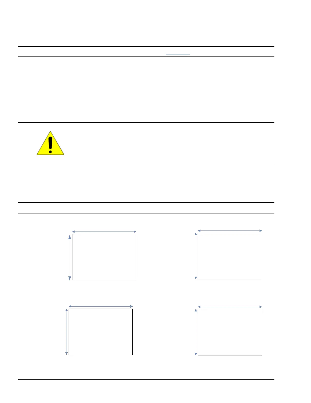
1. Cut an opening in the panel according to the specifications in the following figures.
Note Panel cutout tolerances are +0.50, –0.00 mm (+0.02, –0.00 in).
183.50 mm (7.22 in)
266 mm (10.47 in)
Panel T
hickness
:
1.0 to 5.0
mm
(0.04 to 0.20 in)
Panel T
hickness
:
1.6 to 5.0
mm
(0.06 to 0.20 in)
IC755CxSO6RDx or
IC755CxW07CDx
Panel Cutout
Dimensions
IC755CxS10CDx Panel Cutout Dimensions
302 mm
(
11.89 in)
379 mm (14.92 in)
Panel T
hickness
:
1.6 to 5.0
mm
(0.06 to 0.20 in)
Panel T
hickness
:
1.6 to 5.0
mm
(0.06 to 0.20 in)
IC755CxS12CDx Panel Cutout Dimensions
IC755CxS15CDx Panel Cutout Dimensions