GE_UPS_OPM_SGS_ISG_10K_40K_0US_V070.docx
Installation Guide SG Series 10-20-30-40 UL S
3.9 RPA PARALLEL SYSTEM CONNECTION
WARNING !
This operation must be performed by QUALIFIED SERVICE PERSONNEL ONLY before
the initial start-up.
ENSURE THAT THE UPS INSTALLATION IS COMPLETELY POWERED DOWN.
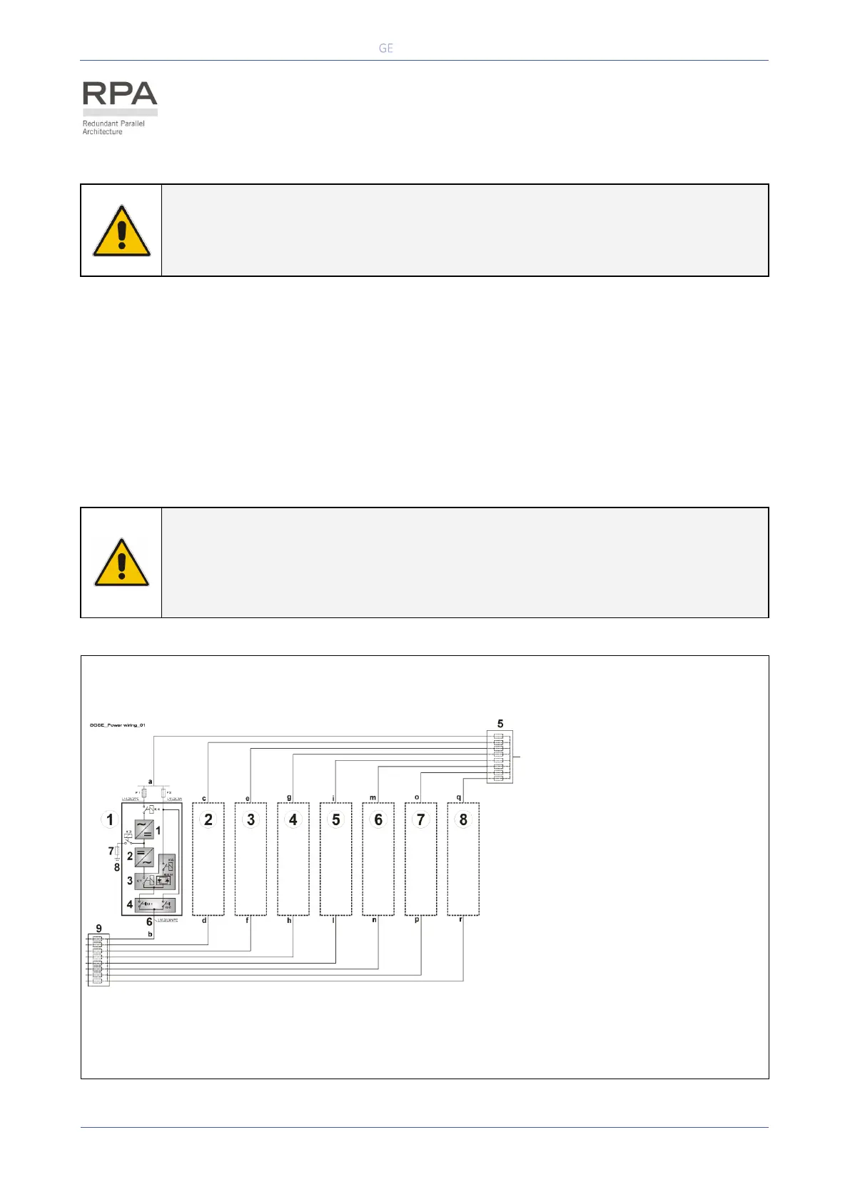
3.9.1 Power wiring of parallel units
To guarantee good Load sharing between the units of a parallel system, we recommend that the cable
length from the input distribution board (5) to the output distribution board (10) is equal for each unit
(a+b = c+d = e+f = g+h = i+l = m+n = o+p = q+r).
Tolerance: +/-10%.
The AC input power of the Bypass must be the same for all units of the parallel system - no phase shift
allowed between units.
NOTE !
It is strongly recommended that no transformers, automatic circuit breakers or fuses
should be inserted between the unit’s output and the Load common bus bars.
However, it is recommended that a disconnection or isolation switch is installed in
order to totally isolate a unit if needed.
Fig. 3.9.1-1 Power wiring of RPA Parallel System
Input Utility Distribution
External Battery fuse or
MCB
Common bus-bar and
Output Load Distribution
 Loading...