GE_UPS_OPM_SGS_ISG_10K_40K_0US_V070.docx
Installation Guide SG Series 10-20-30-40 UL S
Table of contents Page
1 SAFETY RULES ................................................................................................................................................. 6
2 LAYOUT............................................................................................................................................................. 9
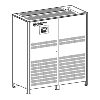
2.1 LAYOUT SG SERIES 10 & 20 ................................................................................................................................................................... 9
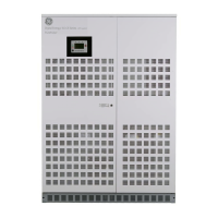
2.2 LAYOUT SG SERIES 30 & 40 .................................................................................................................................................................10
3 INSTALLATION............................................................................................................................................... 11
3.1 TRANSPORT .................................................................................................................................................................................................11
3.1.1 Dimensions and weight ........................................................................................................................................................................ 11
3.2 DELIVERY ......................................................................................................................................................................................................12
3.3 STORAGE .......................................................................................................................................................................................................12
3.3.1 Storage of the UPS .................................................................................................................................................................................. 12
3.3.2 Storage of battery ................................................................................................................................................................................... 12
3.4 PLACE OF INSTALLATION ......................................................................................................................................................................13
3.4.1 UPS location ............................................................................................................................................................................................... 13
3.4.2 Battery location ........................................................................................................................................................................................ 15
3.5 VENTILATION AND COOLING ..............................................................................................................................................................16
3.6 UNPACKING.................................................................................................................................................................................................17
3.7 ELECTRICAL WIRING ...............................................................................................................................................................................19
3.7.1 Utility input connection ......................................................................................................................................................................... 19
3.7.2 Input/output over current protection and wire sizing ............................................................................................................. 20
3.7.3 Battery over current protection and wire sizing ........................................................................................................................ 21
3.8 WIRING CONNECTION ...........................................................................................................................................................................24
3.8.1 Power connections .................................................................................................................................................................................. 24
3.8.2 Power connection with common input utility of SG Series 10 & 20 .................................................................................. 27
3.8.3 Power connection with common input utility of SG Series 30 & 40 .................................................................................. 28
3.8.4 Power connection dual input utility of SG Series 10 & 20 ...................................................................................................... 29
3.8.5 Power connection dual input utility of SG Series 30 & 40 ...................................................................................................... 31
3.8.6 Battery connection of SG Series 10 & 20 ....................................................................................................................................... 33
3.8.7 Battery connection of SG Series 30 & 40 ....................................................................................................................................... 34
3.8.8 Set-up for SG Series 10-20-30-40 when functioning as frequency converter ............................................................. 35
3.9 RPA PARALLEL SYSTEM CONNECTION ...........................................................................................................................................36
3.9.1 Power wiring of parallel units ............................................................................................................................................................. 36
3.9.2 Parallel control bus connection ......................................................................................................................................................... 37
3.9.3 Control bus cable location ................................................................................................................................................................... 39
4 CUSTOMER INTERFACE ................................................................................................................................ 41
4.1 CUSTOMER INTERFACE ..........................................................................................................................................................................41
4.1.1 Serial Port J3 .............................................................................................................................................................................................. 42
4.1.2 Output free potential contacts .......................................................................................................................................................... 42
4.1.3 Programmable input free contacts ................................................................................................................................................. 43
4.1.4 Gen Set Signaling (GEN ON) ................................................................................................................................................................. 43
4.1.5 AUX external Maintenance Bypass .................................................................................................................................................. 43
4.1.6 Auxiliary Power Supply (APS) 24 Vdc ............................................................................................................................................... 43
4.1.7 “EPO - Emergency Power Off” command connection ............................................................................................................. 44
5 NOTES ............................................................................................................................................................. 46
5.1 NOTES FORM ..............................................................................................................................................................................................46
 Loading...