GE_UPS_OPM_SGS_ISG_10K_40K_0US_V070.docx
Installation Guide SG Series 10-20-30-40 UL S
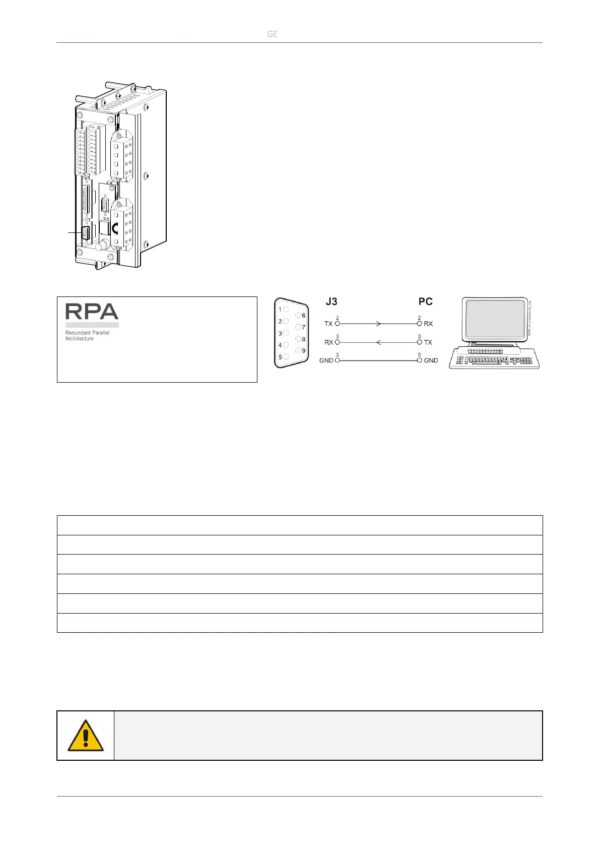
4.1.1 Serial Port J3
Fig. 4.1.1-1 Serial port J3
Serial port J3 - RS-232 (sub D, female 9 pin) that allows:
Total remote management of the system using software GE Power
Diagnostics, GE Data Protection or GE Service Software for system protection
and management of the UPS systems.
Fig. 4.1.1-2 Serial port J3 connection to PC with RS232 1:1 cable DB9m – DB9f
The serial port J3 - RS232 is enabled
on all the units of the parallel system.
4.1.2 Output free potential contacts
The interface board provides 6 voltage free relay contacts giving some UPS critical alarms and
operation mode.
These signals are available either on connector J2- (sub D, female 25 pin) or terminal blocks X1.
The meaning of the alarms on the free contacts in standard configuration (default) is the following:
In case different alarms or operating status are required, they can be configured on the same terminals
via software from the control panel.
The configuration can be changed in Parameters Mode by a trained operator using the appropriate
password.
NOTE !
The programmable signals on X1 and J2 will be disabled with Q1 open, with the
exception of the signals for “16 - Manual Bypass ON” and “26 - EPO”.
4
4
1
3
2
3
2
1
SGT5000_100-150_Customer interface J3_01
J3
 Loading...