B-30 L60 Line Phase Comparison System GE Multilin
B.4 MEMORY MAPPING APPENDIX B
B
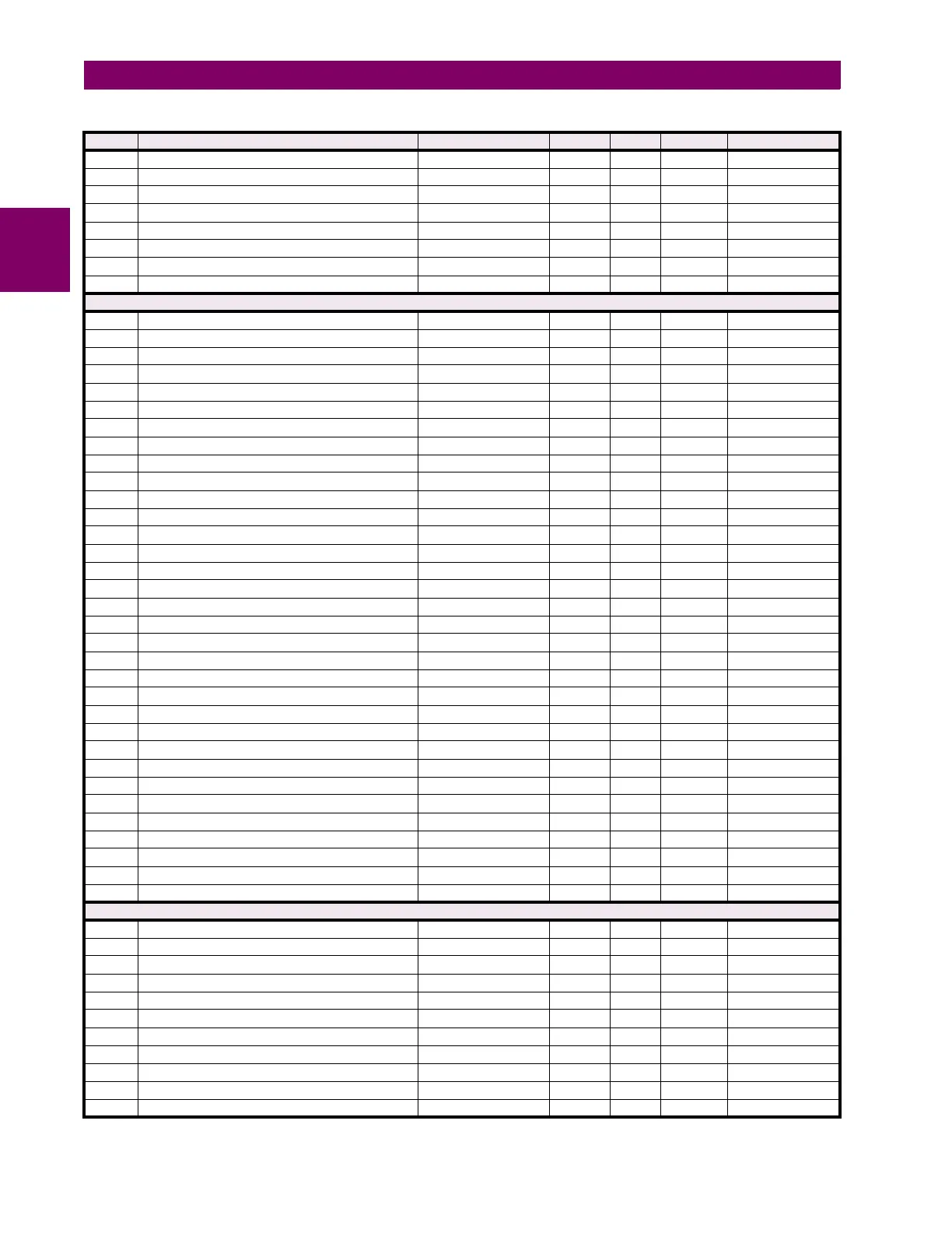
60E3 Breaker 2 Auxiliary Contact 0 to 65535 --- 1 F300 0
60E4 Breaker 2 Supervision Element 0 to 65535 --- 1 F300 0
60E5 Weak-Infeed Keying 0 to 65535 --- 1 F300 0
60E6 Supervision Element 0 to 65535 --- 1 F300 0
60E7 Infeed Pickup Delay 0 to 50 s 0.001 F001 0
60E8 Infeed Reset Delay 0 to 50 s 0.001 F001 35
60E9 Open Breaker Keying Pickup Delay 0 to 50 s 0.001 F001 0
60EA Open Breaker Keying Reset Delay 0 to 50 s 0.001 F001 0
Phase Comparison Trip Scheme (Read/Write Grouped Setting)
60F0 87PC Function 0 to 1 --- 1 F102 0 (Disabled)
60F1 87PC Channel Loss 0 to 500 ms 0.001 F001 0
60F2 87PC Block 0 to 65535 --- 1 F300 0
60F3 87PC Target 0 to 2 --- 1 F109 0 (Self-reset)
60F4 87PC Events 0 to 1 --- 1 F102 0 (Disabled)
60F5 87PC Scheme Select 0 to 8 --- 1 F149 1 (2TL-BL-DPC-3FC)
60F6 87PC Scheme Signal 0 to 1 --- 1 F150 0 (MIXED I_2 - K*I_1)
60F7 87PC Signal Source 0 to 5 --- 1 F167 0 (SRC 1)
60F8 87PC FDL Pickup 0.01 to 15 pu 0.01 F001 50
60FA 87PC FDH Pickup 0.01 to 15 pu 0.01 F001 75
60FB 87PC Mixed Signal K 0 to 0.25 --- 0.01 F001 20
60FE 87PC Phase Delay Ch1 0 to 65.535 ms 0.001 F003 0
6100 87PC Phase Delay Ch2 0 to 65.535 ms 0.001 F003 0
6106 87PC Transient Pickup 0 to 65.535 s 0.001 F003 30
610A 87PC Asymmetry Channel 1 –20 to 20 ms 0.1 F004 0
610E 87PC Asymmetry Channel 2 –20 to 20 ms 0.1 F004 0
6110 87PC Stability Angle 40 to 140 degrees 10 F003 75
6112 87PC Transient Reset 0 to 65.535 s 0.001 F003 30
6113 87PC Received Volts Channel 1 0 to 125 V 0.1 F001 120
6114 87PC Received Volts Channel 2 0 to 125 V 0.1 F001 120
6115 87PC High-Speed Contact 1 0 to 64 --- 1 F490 0
6116 87PC High-Speed Contact 2 0 to 64 --- 1 F490 0
6117 87PC FDL AUX 0 to 65535 --- 1 F300 0
6118 87PC FDH AUX 0 to 65535 --- 1 F300 0
6119 87PC Reset Delay 0 to 200 ms 1 F001 30
611A 87PC Mixed Signal Reference Angle 0 to 359 ° 1 F001 0
611B 87PC Trip Security 0 to 1 --- 1 F534 0 (First Coincidence)
611C 87PC Second Coincidence Timer 10 to 200 ms 1 F001 40
611D 87PC Enhanced Stability Angle 40 to 180 ° 5 F001 110
611E 87PC FDH Supervision 0 to 65535 --- 1 F300 0
611F 87PC Pickup Delay 0 to 50 ms 1 F001 0
6120 87PC Stop Tx 0 to 65535 --- 1 F300 0
6121 87PC Tx Reset Delay 0 to 1000 ms 1 F001 0
CT Failure Detector (Read/Write Setting)
6124 CT Fail Function 0 to 1 --- 1 F102 0 (Disabled)
6125 CT Fail Block 0 to 65535 --- 1 F300 0
6126 CT Fail Current Source 1 0 to 5 --- 1 F167 0 (SRC 1)
6127 CT Fail Current Pickup 1 0 to 2 pu 0.1 F001 2
6128 CT Fail Current Source 2 0 to 5 --- 1 F167 1 (SRC 2)
6129 CT Fail Current Pickup 2 0 to 2 pu 0.1 F001 2
612A CT Fail Voltage Source 0 to 5 --- 1 F167 0 (SRC 1)
612B CT Fail Voltage Pickup 0 to 2 pu 0.01 F001 20
612C CT Fail Pickup Delay 0 to 65.535 s 0.001 F001 1000
612D CT Fail Target 0 to 2 --- 1 F109 0 (Self-reset)
612E CT Fail Events 0 to 1 --- 1 F102 0 (Disabled)
Table B–9: MODBUS MEMORY MAP (Sheet 22 of 55)
ADDR REGISTER NAME RANGE UNITS STEP FORMAT DEFAULT

 Loading...


