B-32 L60 Line Phase Comparison System GE Multilin
B.4 MEMORY MAPPING APPENDIX B
B
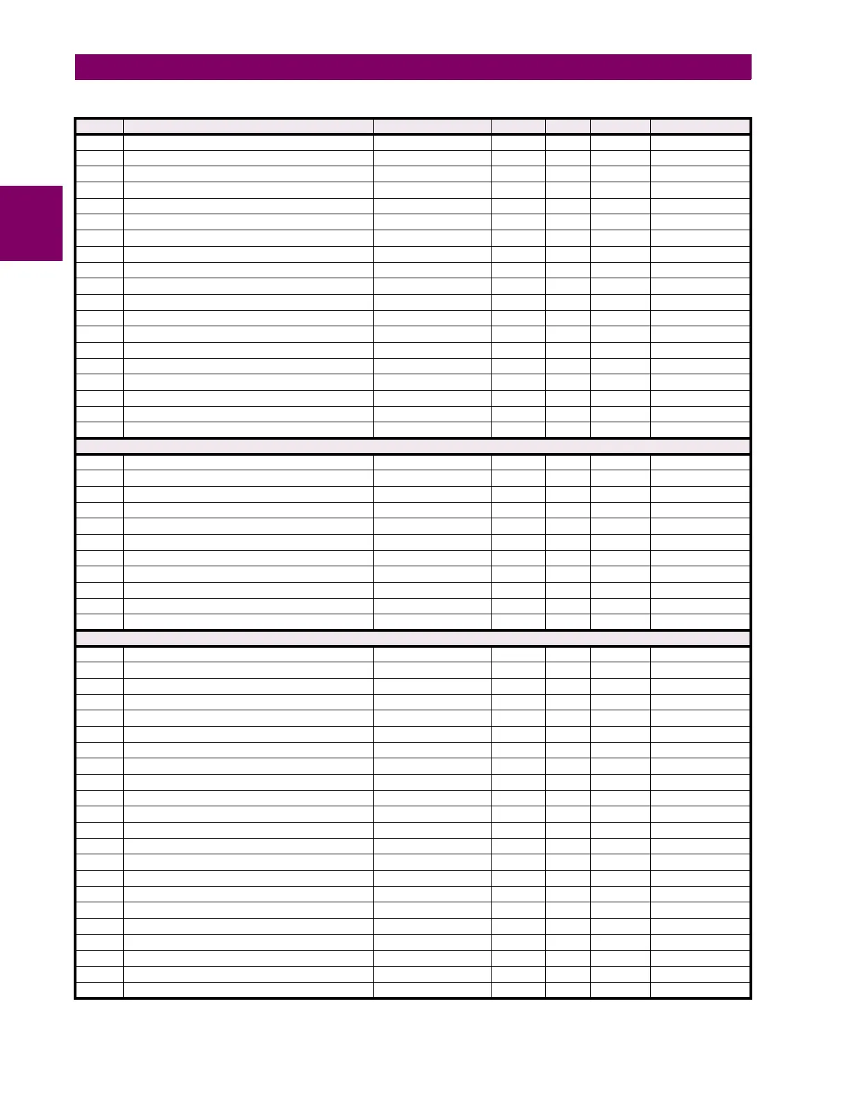
65CD Power Swing Detect Delay 2 Pickup 0 to 65.535 s 0.001 F001 17
65CE Power Swing Detect Delay 3 Pickup 0 to 65.535 s 0.001 F001 9
65CF Power Swing Detect Delay 4 Pickup 0 to 65.535 s 0.001 F001 17
65D0 Power Swing Detect Seal In Delay 0 to 65.535 s 0.001 F001 400
65D1 Power Swing Detect Trip Mode 0 to 1 --- 1 F514 0 (Delayed)
65D2 Power Swing Detect Block 0 to 65535 --- 1 F300 0
65D3 Power Swing Detect Target 0 to 2 --- 1 F109 0 (Self-reset)
65D4 Power Swing Detect Event 0 to 1 --- 1 F102 0 (Disabled)
65D5 Power Swing Detect Shape 0 to 1 --- 1 F085 0 (Mho Shape)
65D6 Power Swing Detect Quad Forward Middle 0.1 to 500 ohms 0.01 F001 6000
65D7 Power Swing Detect Quad Forward Outer 0.1 to 500 ohms 0.01 F001 7000
65D8 Power Swing Detect Quad Reverse Middle 0.1 to 500 ohms 0.01 F001 6000
65D9 Power Swing Detect Quad Reverse Outer 0.1 to 500 ohms 0.01 F001 7000
65DA Power Swing Detect Outer Right Blinder 0.1 to 500 ohms 0.01 F001 10000
65DB Power Swing Detect Outer Left Blinder 0.1 to 500 ohms 0.01 F001 10000
65DC Power Swing Detect Middle Right Blinder 0.1 to 500 ohms 0.01 F001 10000
65DD Power Swing Detect Middle Left Blinder 0.1 to 500 ohms 0.01 F001 10000
65DE Power Swing Detect Inner Right Blinder 0.1 to 500 ohms 0.01 F001 10000
65DF Power Swing Detect Inner Left Blinder 0.1 to 500 ohms 0.01 F001 10000
Load Encroachment (Read/Write Grouped Setting)
6700 Load Encroachment Function 0 to 1 --- 1 F102 0 (Disabled)
6701 Load Encroachment Source 0 to 5 --- 1 F167 0 (SRC 1)
6702 Load Encroachment Minimum Voltage 0 to 3 pu 0.001 F001 250
6703 Load Encroachment Reach 0.02 to 250 ohms 0.01 F001 100
6704 Load Encroachment Angle 5 to 50 degrees 1 F001 30
6705 Load Encroachment Pickup Delay 0 to 65.535 s 0.001 F001 0
6706 Load Encroachment Reset Delay 0 to 65.535 s 0.001 F001 0
6707 Load Encroachment Block 0 to 65535 --- 1 F300 0
6708 Load Encroachment Target 0 to 2 --- 1 F109 0 (Self-reset)
6709 Load Encroachment Events 0 to 1 --- 1 F102 0 (Disabled)
670A Reserved (6 items) 0 to 65535 --- 1 F001 0
Trip Output (Read/Write Setting)
6800 Trip Mode 0 to 2 --- 1 F195 0 (Disabled)
6801 Trip 3-Pole Input1 0 to 65535 --- 1 F300 0
6802 Trip 3-Pole Input2 0 to 65535 --- 1 F300 0
6803 Trip 3-Pole Input3 0 to 65535 --- 1 F300 0
6804 Trip 3-Pole Input4 0 to 65535 --- 1 F300 0
6805 Trip 3-Pole Input5 0 to 65535 --- 1 F300 0
6806 Trip 3-Pole Input6 0 to 65535 --- 1 F300 0
6807 Trip 1-Pole Input1 0 to 65535 --- 1 F300 0
6808 Trip 1-Pole Input2 0 to 65535 --- 1 F300 0
6809 Trip 1-Pole Input3 0 to 65535 --- 1 F300 0
680A Trip 1-Pole Input4 0 to 65535 --- 1 F300 0
680B Trip 1-Pole Input5 0 to 65535 --- 1 F300 0
680C Trip 1-Pole Input6 0 to 65535 --- 1 F300 0
680D Trip Reclose Input1 0 to 65535 --- 1 F300 0
680E Trip Reclose Input2 0 to 65535 --- 1 F300 0
680F Trip Reclose Input3 0 to 65535 --- 1 F300 0
6810 Trip Reclose Input4 0 to 65535 --- 1 F300 0
6811 Trip Reclose Input5 0 to 65535 --- 1 F300 0
6812 Trip Reclose Input6 0 to 65535 --- 1 F300 0
6813 Trip Force 3-Pole 0 to 65535 --- 1 F300 0
6814 Trip Pilot Priority 0 to 65.535 s 0.001 F001 0
6815 Breaker Phase A Open 0 to 65535 --- 1 F300 0
Table B–9: MODBUS MEMORY MAP (Sheet 24 of 55)
ADDR REGISTER NAME RANGE UNITS STEP FORMAT DEFAULT

 Loading...


