10
Accessories for Drawout Breakers (cont.)
Table 10.1 WP-32 / 40 / 50 circuit breakers
Table 10.2
Field Installable Remote Close Accessory kit catalog numbers
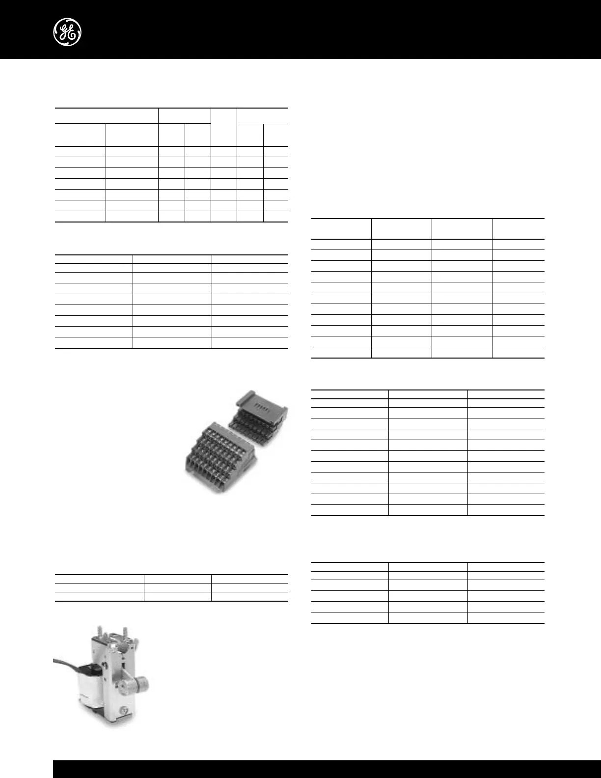
Secondary Disconnect (Field installable kit available)
Inputs and outputs to the circuit breaker are wired through
secondary disconnects located
on the top of the breaker. The
plug-style secondary discon-
nects engage mating discon-
nects in the breaker cubicle
when the breaker is in the
TEST or CONNECT position.
Up to 72 dedicated points are
available so that all breaker
accessories can be wired to dedicated disconnect points.
Refer to the breaker wiring diagrams shown on pages 30
and 31 for breaker accessory wiring.
Table 10.3 Field Installable Secondary Disconnect kit catalog
numbers
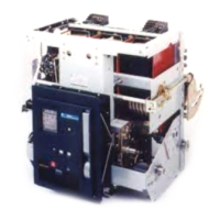
Shunt Trip (Field installable kit
available)
The shunt trip allows remote
electrical tripping of the circuit
breaker. It is usually controlled by
a switch or push button and may
also be used in conjunction with
protective relays for automatic
tripping (the breaker trip units do
WP-08 / 16 / 20 WP-32 / 40 / 50
Breaker side (female) WPSDSUBF1 WPSDSUBF1
Cell side (male) WPSDSUBM1 WPSDSUBM2
Control voltage WP-08 / 16 / 20 WP-32 / 40 / 50
120Vac 60Hz WPRCSF60120 WPRCLF60120
120Vac 50Hz WPRCSF50120 WPRCLF50120
240Vac 60Hz WPRCSF60240 WPRCLF60240
240Vac 50Hz WPRCSF50240 WPRCLF50240
48Vdc WPRCSFDC048 WPRCLFDC048
110Vdc WPRCSFDC110 WPRCLFDC110
125Vdc WPRCSFDC125 WPRCLFDC125
250Vdc WPRCSFDC250 WPRCLFDC250
Spring charging
Closing
motor (amps)
coil
Nominal Charge / Charging
control Voltage
inrush
close fuse time
voltage range Inrush Sustained
(amps)
(amps) (sec)
120v-60Hz 104-127 25.0 8.1 16.0 15 1.5
120v-50Hz 104-127 25.0 8.1 16.0 15 1.5
240v-60Hz 208-254 11.7 3.5 7.0 15 1.3
240v-50Hz 208-254 11.7 3.5 7.0 15 1.3
48Vdc 38-56 22.0 16.5 15.0 15 2.0
110/125Vdc 100-140 25.0 7.0 4.0 15 1.7
250Vdc 200-280 13.0 3.2 3.0 15 1.7
not require the use of a shunt trip). The shunt trip coil is rated
for intermittent duty and is supplied with an auxiliary switch
contact that automatically removes control power following a
breaker trip. A shunt trip is always supplied on electrically
operated breakers. A redundant or 2nd shunt trip is available
on all frame size breakers for special control applications. The
second shunt trip occupies the same space as the undervoltage
device. See Table 10.4 for shunt trip operating characteristics.
Table 10.4 Shunt trip operating characteristics
Table 10.5
Field
Installable
Shunt Trip 1 kit catalog numbers
Table 10.6
Field
Installable
Shunt Trip 2 kit catalog numbers
Spring Charging Motor
The spring charging motor is supplied on all electrically
operated breakers. The breaker closing springs are charged
automatically when control voltage is applied to the breaker.
When the springs are fully charged, a cutoff switch de-ener-
gizes the motor. The closing springs will recharge automati-
cally after the breaker closes unless an external switch con-
Control voltage WP-08 / 16 / 20 WP-32 / 40 / 50
120Vac 60Hz WPS2SF60120 WPS2LF60120
240Vac 60Hz WPS2SF60240 WPS2LF60240
24Vdc WPS2SFDC024 WPS2LFDC024
110/125Vdc WPS2SFDC125 WPS2LFDC125
250Vdc WPS2SFDC250 WPS2LFDC250
Control voltage WP-08 / 16 / 20 WP-32 / 40 / 50
70Vac 60Hz WPS1SF60070 WPS1LF60070
120Vac 60Hz WPS1SF60120 WPS1LF60120
120Vac 50Hz WPS1SF50120 WPS1LF50120
208Vac 60Hz WPS1SF60208 WPS1LF60208
208Vac 50Hz WPS1SF50208 WPS1LF50208
240Vac 60Hz WPS1SF60240 WPS1LF60240
240Vac 50Hz WPS1SF50240 WPS1LF50240
24Vdc WPS1SFDC024 WPS1LFDC024
48Vdc WPS1SFDC048 WPS1LFDC048
110/125Vdc WPS1SFDC125 WPS1LFDC125
250Vdc WPS1SFDC250 WPS1LFDC250
Nominal control Operating Inrush Sealed
voltage voltage range, V current, A current, A
70V, 60Hz 70-127 3.75 3.75
120V, 60Hz 95-127 12.3 10.8
120V, 50Hz 95-127 7.6 6.7
208V, 60Hz 165-220 3.2 2.6
208V, 50Hz 165-220 3.8 3.1
240V, 60Hz 190-254 3.9 3.4
240V, 50Hz 190-254 4.7 4.1
24Vdc 14-30 8.3 8.3
48Vdc 28-60 4.5 4.5
110/125Vdc 70-140 2.0 2.0
250Vdc 140-280 1.0 1.0