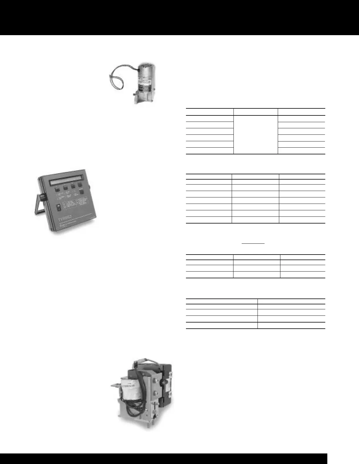
tact is wired into the spring
charging circuit. If control
power is lost during the spring
charging cycle, spring charging
can be completed using the
integral manual pump handle.
The optional remote charge indi-
cator contact can be supplied to
provide a contact closure when the springs are fully
charged. Refer to Tables 9.1 and 10.1 for spring charging
motor operating characteristics.
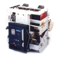
Test Kit
The test kit, catalog number TVRMS2, is a portable, battery-
or ac-powered unit that is used for trip unit health checks
and also provides functional
trip and no-trip tests of the
trip unit. It can be used to
defeat the ground fault func-
tion of the trip unit when
performing high current
tests on the circuit breaker.
The test kit supplies 24Vdc
auxiliary power for cold set-
up and viewing of trip targets
on trip units not equipped with on-board batteries. The dis-
play on the test kit can be used to verify pickup and delay
settings that have been programmed into the trip unit. This
test kit is designed for use with all Power+™ , MicroVersaTrip
Plus™
and MicroVersaTrip PM™ trip units.
Undervoltage Device (Field installable kit available)
The undervoltage device protects against harmful drops or
complete loss of voltage by automatically tripping the break-
er. The undervoltage device can be used to sense the drop
or loss of bus voltage through the use of voltage transform-
ers or it can monitor a control voltage source. This device is
set to pick-up at approximately 85% of rated voltage and
will drop out instantaneously between 30 and 60% (nonad-
justable) of rated voltage. An electronic module on the
undervoltage device provides accurate and repeatable oper-
ating characteristics. The
undervoltage device is avail-
able with an optional static
time delay unit. This unit
offers a field-adjustable two- to
six-second delay between
undervoltage occurrence and
breaker trip, thus preventing
potential nuisance tripping
due to momentary loss of volt-
age. The time delay unit is
11
Accessories for Drawout Breakers (cont.)
mounted externally to the breaker. It is rated 125Vdc,
250Vdc, 208Vac or 240Vac, 50/60Hz. For any other AC
source voltage, a control power transformer with a 240v sec-
ondary, rated at least 100VA, is required. Refer to Table 11.1
for undervoltage device operating characteristics.
Table 11.1 Undervoltage device operating characteristics
Table 11.2
Field
Installable
Undervoltage Device kit catalog numbers
Table 11.3
Field Installable T
ime Delay Undervoltage Device kit catalog
numbers (order Static Time Delay Unit separately)
Table 11.4 Static Time Delay catalog numbers
Zone Selective Interlocking (Optional)
Zone selective interlocking is available for either ground
fault only, or both ground-fault and short-time functions.
The zone selective interlocking feature requires a zone
selective interlock module (ZSIM) catalog number TIM1.
The module is an intermediate control device used between
upstream and downstream circuit breakers to communicate
with the short-time and ground-fault zone selective interlock
functions of the MicroVersaTrip Plus and MicroVersaTrip
PM units. The module requires 120/208/240 Vac, 15 VA
maximum. Refer to page 22 for more details.
Nominal Control Voltage Catalog Number
125Vdc TAKYUVT-1
250Vdc TAKYUVT-2
240Vac TAKYUVT-4
208Vac TAKYUVT-5
Control voltage WP-08 / 16 / 20 WP-32 / 40 / 50
208/240Vac 50/60Hz WPUVSFTD240 WPUVLFTD240
125Vdc WPUVSFTD125 WPUVLFTD125
250Vdc WPUVSFTD250 WPUVLFTD250
Control voltage WP-08 / 16 / 20 WP-32 / 40 / 50
120Vac 50/60Hz WPUVSF56120 WPUVLF56120
240Vac 50/60Hz WPUVSF56240 WPUVLF56240
24Vdc WPUVSFDC024 WPUVLFDC024
48Vdc WPUVSFDC048 WPUVLFDC048
110Vdc WPUVSFDC110 WPUVLFDC110
125Vdc WPUVSFDC125 WPUVLFDC125
250Vdc WPUVSFDC250 WPUVLFDC250
Nominal control voltage Operating voltage range Holding current, A
120Vac 0.15
240Vac
Pickup at 80% of
0.07
24Vdc
nominal control
0.58
48Vdc
voltage, drop out at 30-
0.32
110/125Vdc
60% (non-adj) of
0.15
250Vdc
nominal control voltage
0.07