Designationonthenameplate Stickerontheterminalbox
Y/YY
Compressorswiththismarkingaresuitablefordirectorpartialwindingstart.Themotorwindingis
subdividedintotwoparts:Part winding 1 = 50% and part winding 2 = 50%.Thiswindingdivision
reducesthestart-upcurrentneededforapartwindingstarttoapprox.50%ofthatforadirectstart.
INFO A mechanical unloaded start with bypass solenoid valve is
notrequired.
5| Electrical connection
5.1 Information for contactor and motor contactor selection
Allprotectionequipment,switchingandmonitoringdevicesmustcomplywiththelocalsafetyregula-
tionsandestablishedspecications(e.g.VDE)andregulationsaswellasthemanufacturer’sspeci-
cations.Motorprotectionswitchesarerequired!Motorcontactors,feedlines,fusesandmotor
protectionswitchesmustberatedaccordingtothemaximumoperatingcurrent(seenameplate).
Formotorprotection,useacurrent-independent,time-delayedoverloadprotectiondeviceformonitor-
ingallthreephases.Adjusttheoverloadprotectiondevicesothatitmustbeactuatedwithin2hours
at1.2timesthemaximumworkingcurrent.
INFO
Connectthecompressormotorinaccordancewiththecircuitdiagram
(seeinsideofterminalbox).
Usesuitablecableentrypointofthecorrectprotectiontype(see
nameplate)forroutingcablesintotheterminalbox.Insertthestrain
reliefsandpreventchafemarksonthecables.
Comparethevoltageandfrequencyvalueswiththedataforthe
mainspowersupply.
Only connect the motor if these values are the same.
DANGER Risk of electric shock! High voltage!
Only carry out work when the electrical system is disconnected
from the power supply!
5 Electrical connection
ATTENTION When attaching accessories with an electrical cable, a minimum
bending radius of 3 x the cable diameter must be maintained for
laying the cable.
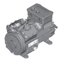
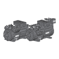
5.2 Standard motor, design for direct or part winding start
 Loading...