22
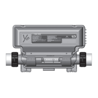
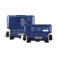
Electrical wiring: European model in.yt
PJ2
PJ1
N
L1
G
N
PJ2
PJ1
L1
L2
G
L3
PJ2
PJ1
L1
L2
G
N
PJ2
PJ1
L1
L2
L3
G
Refer to wiring diagram in the enclosure box lid for more information�
Warning
in�yt�ce models must always be connected to a circuit protected by a Residual-Current Device (RCD) having
a rated operating residual-current not exceeding 30 mA� Correct wiring of the electrical service box, RCD, and
pack terminal block is essential! Check your electrical code for local regulations� Only copper wire should be
used, never aluminum�
Connect PJ1 between
P7 and P13�
Connect PJ2 between
P10 and P74�
Connect PJ1 between
P7 and P10�
Connect PJ2 between
P13 and P74�
Connect PJ1 between
P7 and P10�
Connect PJ2 between
P13 and P74�
Connect PJ1 between
P7 and P10�
Connect PJ2 between
P11 and P13�
1-phase 2-phase 3-phase Delta (no neutral) 3-phase with single neutral
Insert each wire into the appropriate socket of the main entry terminal block according to the color code indicated on the
sticker� Use a flat-head screwdriver to tighten the screws on the terminal�
After making sure wires are securley connected, push them back into the box and replace the cover� Do not over tighten
cover screws (torque to 8 in� lb max {0�9 N�m})�
Connect the bonding conductor to the bonding lug on the front of the spa pack (a grounded electrode conductor should
be used to connect the equipment grounding conductors)�
Electrical wiring
 Loading...