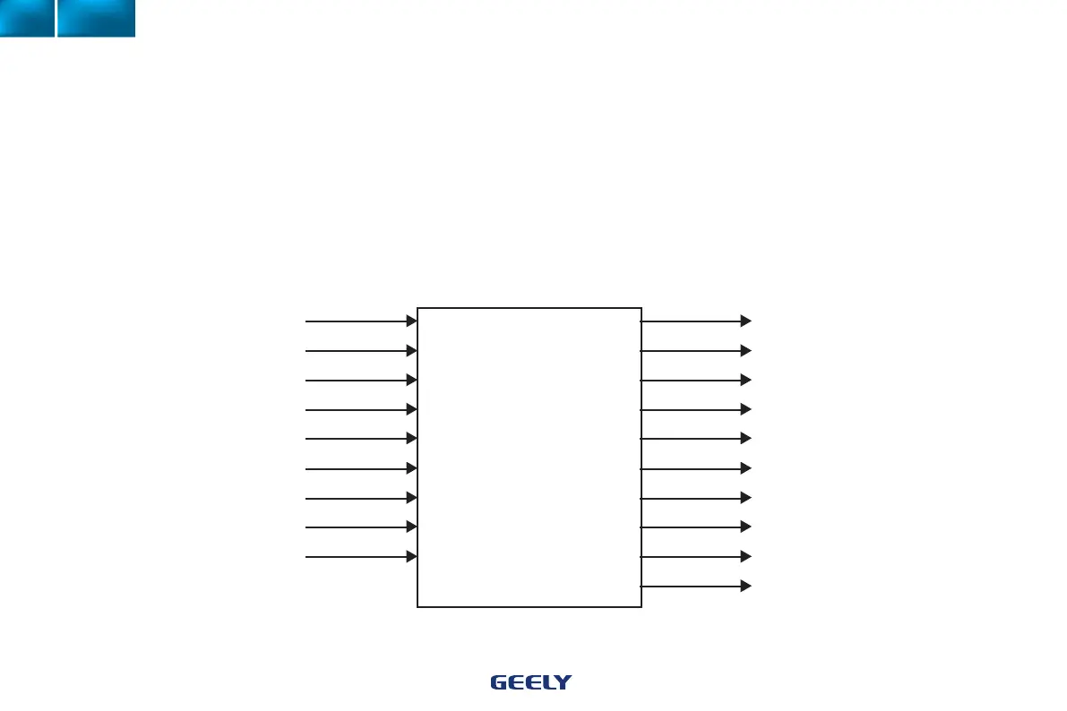
Pressure temperature sensor Injector
Crank angle sensor Ignition coil
Coolant temperature sensor Primary relay
Throttle position sensor Stepper motor
Oxygen sensor Fuel pump
Cam position sensor Cooling fan motor
Battery (voltage signal) Air conditioner
Knock sensor Malfunction Indication Light
A/C condenser temperature sensor Canister control valve
Failure diagnosis
Electronic Injection System Control Diagram
MR479Q. MR479QA. MR481QA.JL481Q engines use ECU controlled electronic ignition system without distributors, and are ignited in groups and sequence.
Electronic control unit (ECU) is composed of input, output channels and a microcomputer. Signals collected by sensors are rst sent to the input channel
for processing and A/D transformation. Then the microcomputer performs complex operation on the processed signals and sends control signal through
the output channel to actuators to initiate the electronic fuel supply and ignition. Specic system control functions are illustrated in the chart below:
1. Fuel injection volume
2. Ignition timing
3. Idle control
4. Fuel pump control
5. Cooling fan
6. A/C cutoff when accelerating
7. Canister fuel duty ratio
8. Self diagnosis
9. A/C relay
105
Part II