- 5A at 250Vac/30Vdc relay
- 24V, 10V at 20mA logic
- triac 20...240Vac, 1A ±10%
- Digital insulated 24Vac/dc
- 5A/250Vac relay only
- 5A at 250Vac/30vdc relay
- 24V, 10V at 20mA logic
- continuous 0…10V, 0/4…20mA
- analog 0…10V, 0/4…20mA for
transmission, resolution 12 bit
- input from current transformer
50mAac, 10 Ω 50/60 Hz
- logic input 24V, 5mA or from
no-voltage contac
- Digital insulated 24Vac/dc
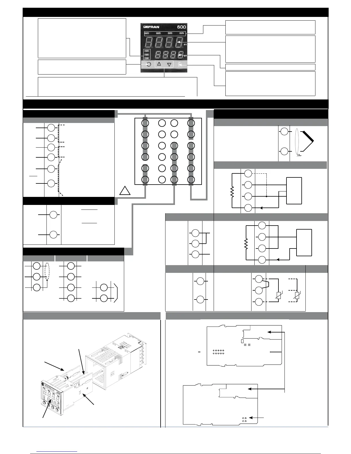
• Identification of boards
Power board - Solder side
Select transmitter
voltage
Select signal at
contact 3
CPU board - Component side
PT100
+VT
24V
15V
10V
5V
1,23V
R20
S2
N.B. : you can keep the OUT1 relay energized at power-up by
inserting jumper S2 and removing resistance R20.
IN/OUT boards
(see appendix)
Standard:
100...240Vac ± 10%
Optional:
11...27Vac/Vdc ± 10%
Max. power 8VA; 50/60 Hz
4 • CONNECTIONS
• Ammeter outputs/input
6
5
4
3
2
1
7
8
9
10
11
12
18
17
16
15
14
13
19
20
21
22
23
24
-
+
Out2
Out1
• Power Supply
23
24
~
~
TOP
-
+
Out3 (Al2)
Ing. T.A.
!
PWR
3 • DESCRIPTION OF FACEPLATE
• Serial line / output 4
4...20mA
Connect at 20mA input
Use wires of
adequate diameter
(min. 1mm
2
)
PT100, JPT100,
PTC, NTC
• Pt100 / PTC / NTC
• Device structure
3
1
2
Pt100 3 wires
PTC / NTC
/ Pt100 2 wires
Available thermocouples:
J, K, R, S, T
(B, E, N, L, U, G, D, C custom
linearization is available)
- Observe polarities
- For extensions, use the correct
compensating cable for the type
of TC used
+
-
• TC Input
2
1
4
2
3
1
+ 24V o 15V
VT
-
+
+
S
-
Ri = 50Ω
4
2
3
1
+ 24V o 15V
VT
-
+
+
-
Ri = 50Ω
T
T
• Linear input with 3-wire transmitter
• Inputs
• Input 1 linear with transmitter 2 wires
DISPLAY
POWER
SERIAL INTERFACE/OUT4
CPU
Linear
input
in dc
current
20mA,
Ri = 50Ω
Linear input in
dc voltage
60mV, 1V
Ri > 1MΩ
5V, 10V
Ri > 10KΩ
2
1
+
-
• Linear input (I)
4
1
2
-
+
• Linear input (V)
19
21
20
22
6
5
User configurable generic output
“Inc” and “Dec” key
Press to increment (decrement) any numerical parameter •• Increment (decrement) speed
is proportional to time key stays pressed •• The operation is not cyclic: once the maximum
(minimum) value of a field is reached, the value will not change even if the key remains pressed.
Automatic/Manual adjustment selection
Active only when PV display visualises
the process variable
Function indicators
Indicates modes of operation
MAN/AUTO = OFF (automatic control)
ON (manual control)
SETPONT1/2 = OFF (IN1 = OFF - local Setpoint 1)
ON (IN1 = ON - local Setpoint 2)
SELFTUNING = ON (enabled Self)
OFF (disabled Self)
PV Display: Indication of process variable
Error Indication: LO, HI, Sbr, Err
LO= the value of process variable is < di LO_S
HI= the value of process variable is > di HI_S
Sbr= faulty sensor or input values higher than max. limits
Err= PT100 third wire opened for PT100, PTC or input
values lower than min. limits (i.e.: TC wrong connection)
Function key
Gives access to the various configuration phases ••
Confirms change of set parameters and browses next or
previous parameter (if Auto/Man key is pressed)
SV display: Indication of setpoint
Indication of output states
OUT 1 (AL1); OUT 2 (Main); OUT 3 (HB); OUT 4 (HB)
Cencal Out 4Modbus
5A at 250Vac/30Vdc
relay
Standard
configuration
9
10
11
+
-
TX
RX
-
+
12
9
10
11
12
RS485 isolated serial line See serial card data sheet for Cencal configuration
11
A
(Data +)
B
(Data -)
2 80336L_MHW_600_07-2011_ENG
2 / 31