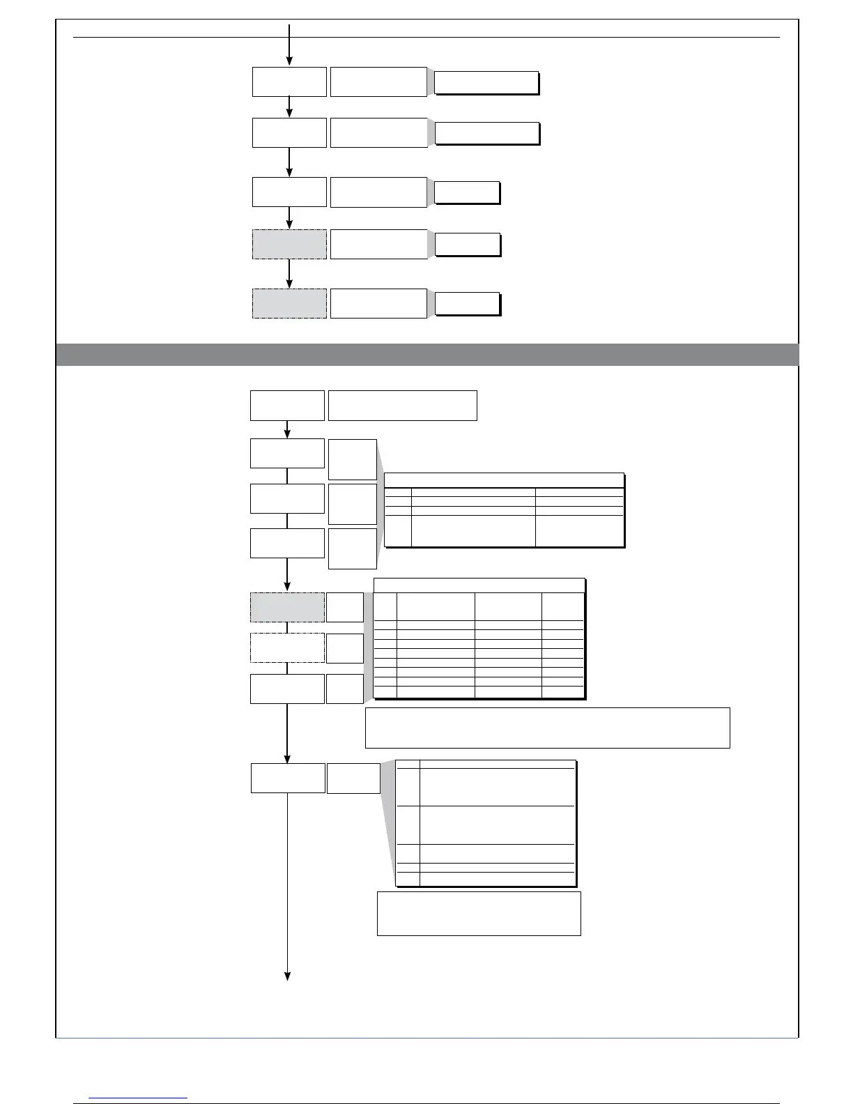
lo.l
of.2
xs.2
l5.2
Minimum limit auxiliary
input scale
Offset correction
of aux input
0.0 ... 999.9
Maximum limit auxiliary
input scale
0.0 ... 999.9
-99.9 ... 99.9
scale points
Lower limit for setting SP
and absolute alarms
Lo.S ... Hi.S
Upper limit for setting SP
and absolute alarms
Lo.S ... Hi.S
• Out
Out
Output settings
Select
reference
signal for
alarm 1
AL.1.r, AL.2.r, AL.3.r
Select
reference
signal for
alarm 2
Select
reference
signal for
alarm 3
AL.x.r Variable to be compared Reference setpoint
0 PV (Process variable) AL
1 SSP (active setpoint) AL (only absolute)
2 PV (process variable) AL (only relative and
referred to SP1 with
multiset function)]
Alarm
type 1
Alarm
type 2
Alarm
type 3
+8 to disable on power up until first interception
+16 to latch alarm
+ 32 Hys becomes delay time when alarm trips (0...999 sec.) (excluding symmetrical absolute)
+ 64 Hys becomes delay time when alarm trips (0...999 min.) (excluding symmetrical absolute)
AL.x.t Direct (high limit) Absolute or Normal
Inverse (low limit) relative to
Symmetrical
active setpoint (window)
0 direct absolute normal
1 inverse absolute normal
2 direct relative normal
3 inverse relative normal
4 direct absolute
symmetrical
5 inverse absolute
symmetrical
6 direct relative
symmetrical
7 inverse relative
symmetrical
AL.1.t, AL.2.t, AL.3.t
HB alarm
function
+ 0 assigned to Out1 (only for Hb_F= 0, 1, 2)
+ 4 assigned to Out2 (only for Hb_F= 0, 1, 2)
+ 12 assigned to Out4 (only for Hb_F= 0, 1, 2)
+16 inverse HB alarm
a1.r
a2.r
a3.r
a1.t
xb.f
a2.t
a3.t
xi.l
Val. Function description
0 Relay, logic output: alarm active
on load current level lower
than setpoint during the
ON time of the control output
1 Relay, logic output: alarm active
on load current level higher
than setpoint during the
OFF time of the control output
2 Alarm active if one of functions 0 and 1
is true (OR logic between 0 and 1) (*)
3 Continuous heat alarm (**)
7 Continuous cool alarm (**)
(*) minimum setting is fixed at 12% of amperometric full scale
(**) As type 0 without reference to cycle time
Notes:
- The HB alarm is disabled if assigned to a rapid output (except codes 3 and 7)
- When the CT input is present, faceplate LED OUT3 always indicates the state of the HB alarm.
780336L_MHW_600_07-2011_ENG
7 / 31