4-22
11-19
Speed loop integration
gain
0 ~65535 800
11-20
Speed loop differential
gain
0 ~65535 0
11-21 Stop Key Selection
0: Enable Stop Key when Run
Command
not from Keypad
1: Disable Stop Key when Run
0
Group12 Digital Display & Monitor functions
No. Description Range
Factory
Unit Note
12-00
Extended Display Mode
00000 ~77777.
Each digit can be set to 0 to 7
00321 - *1
0: Default display
(frequency¶meters)
6:Analog Signal Input. (AVI)
7:Analog Signal Input. (ACI)
12-01
PID Feedback Display
format
0 - *1
1:One decimal Place (xx.x)
2:Two Decimal Places (x.xx)
12-02
PID Feedback Display
Unit Setting
0 - *1
12-03
Custom Units (Line
Speed) Value
0~65535 1500/1800 rpm *1
12-04
Custom Units (Line
Speed) Display Mode
0:Drive Output Frequency is Displayed
0 - *1
1:Line Speed. Integer.(xxxxx)
2:Line Speed..One Decimal Place
(xxxx.x)
3:Line Speed.Two Decimal Places
(xxx.xx)
4:Line Speed.Three Decimal Places
(xx.xxx)
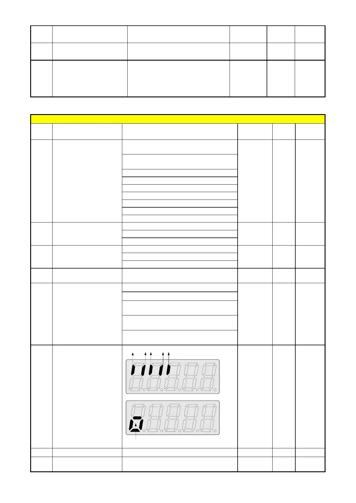
12-05
Inputs and output
Logic status display
( S1 to S5) & RY1
----- - *4
12-07
0 %

 Loading...


