40 917001/CP0905
Allow sufficient time for the skid-steer loader alternator to build-up a charge in
the battery before attempting to operate the loader or shut the engine off.
Changing Attachments
To prevent unexpected release of the attach-
ment from the hitch, be sure to properly
secure the hitch latch pins by rotating the latch levers all the way
(manual All-Tach™ hitch) or by ensuring that the pin flags are all
the way to the outside (Power-A-Tach™ hitch).
The skid-steer loader features either a manual or a power hitch for mounting a
bucket or other attachment conforming to SAE Standard J2513.
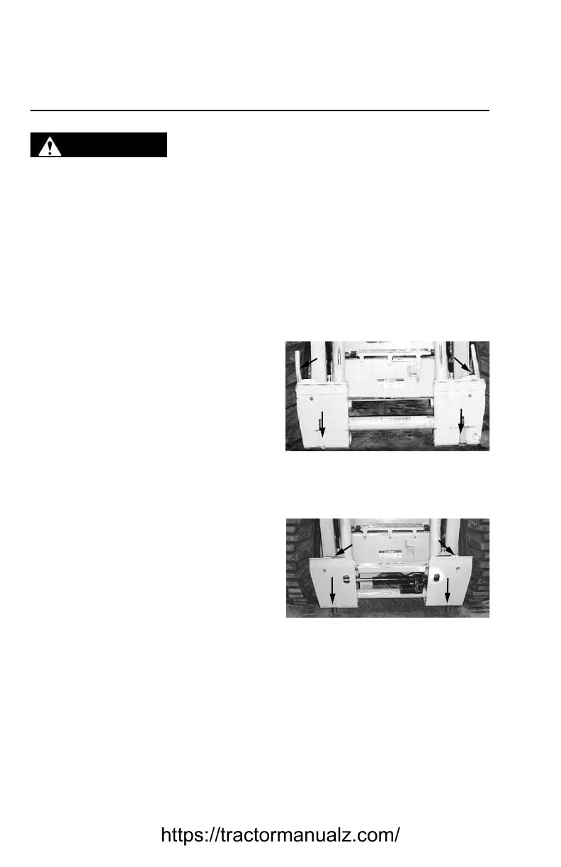
On a manual All-Tach hitch (Figure 20), two latch levers engage the latch pins to
secure the attachment. On a Power-A-Tach hitch (Figure 21), a switch on the left
control panel activates the latch pins to secure the attachment.
Connecting Attachments
1. Manual hitch: Rotate the latch levers
until the handles are horizontal to
engage the lock pins.
2. Power hitch: Activate the switch to
unlock the hitch and fully retract the
latch pins.
3. Start the loader engine. Be sure the lift
arm is lowered and in contact with the
loader frame.
4. Align the loader squarely with the back
of the attachment.
5. Tilt the hitch forward until the top edge
of the hitch is below the flange on the
back side of the attachment and cen-
tered between the vertical plates.
6. Slowly drive the loader forward and, at the same time, tilt the hitch back to
engage the flange on the back side of the attachment.
7. Stop forward travel when the flange is engaged, but continue to tilt the hitch
back to lift the attachment off the ground.
WARNING
Figure 20 Manual Hitch –
disengaged
1. Latch Lever
2. Latch Pins
1
1
2
2
Figure 21 Power Hitch –
disengaged
1. Pin Flags
2. Latch Pins
1
1
2
2
https://tractormanualz.com/
 Loading...