ELECTRICAL CONNECTIONS
!
!
!
!
!
!
!
!
Implement the electrical engine blocks by working on the fuel pump and
the starter motor.
Connect the supply power positive of the 7590T alarm system to the
vehicle battery or to one of its derivations.
Connect the supply power negative of the 7590T alarm system to the
vehicle's metallic frame (all 2 BLACK wires marked M).
Connect ALWAYS one of the GREEN/BROWN wires of the alarm wiring
harness to the doors switch.
Connect (if necessary) the other GREEN/BROWN wire of the alarm wiring
harness to the doors switch.
Connect ALWAYS the BLACK wire marked V of the alarm wiring harness
to the bonnet switch.
Before programming the system, .
For the CDL connections see at the diagram in the next pages.
The index reported below refers to the electrical scheme of alarm cable in the
next page.
Before effecting all electrical connections, disconnect the NEGATIVE
BATTERY POLE and connect again when mounting as terminated.
make all the electrical connection
NOTE: (available) diagrams for every specific car, must be required to
the zone dealer.
NOTE: The BLACK two pin connectors of the alarm wiring harness are
for the electronic key and led connections.
Negative
Positive
Engine immobilization 1
Engine immobilization 1
Positive under key
Door pin switches
Bonnet/boot switches
Positive alarm ON
External sensor input
Negative control for supplementary siren
Self powered siren
Turn signals
Negative output for electically controlled
boot opening
CDL (see diagram)
N°2
BLACK marked
BLACK marked
N°2 BLACK marked B
BLACK marked G
N°2
N°2 BLACK marked V
PINK
GREEN/BLACK
YELLOW/BLACK
BLUE
N°2 ORANGES
GREY-BLACK
YELLOW/BLUE RED/BLUE
YELLOW/BROWN RED/BROWN
YELLOW/GREY RED/GREY
BLACK marked M
R
N°2 H
GREEN/BROWN
FUNCTION WIRE COLOUR
ELECTRONIC KEY
YELLOW-GREY
BLACK marked G
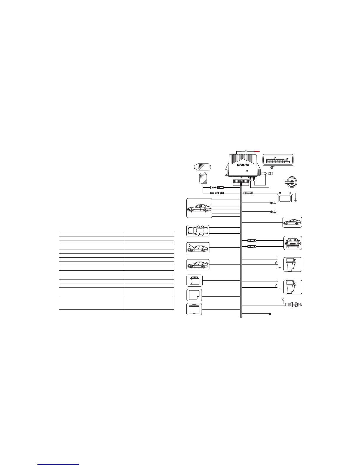
+30
EARTH
EARTH
ORANGE
ORANGE
15A
+
Battery
12 VOLT
YELLOW-BLUE
YELLOW-BROWN
RED-GREY
RED-BROWN
RED-BLUE
WIRING DIAGRAM
ART.7590
Negative control for
supplementary siren
YELLOW-BLACK
GREY-BLACK
BLUE
Self-powered siren output
GREEN-BROWN
GREEN-BROWN
Doors push buttons
See locks diagrams
Engine immobilisation 1
Engine immobilisation 2
8A
MAX !
8A
MAX !
Positive to alarm
activated (700mA max.)
BLACK marked V
BLACK marked V
BLACK marked R
BLACK marked M
BLACK marked M
BLACK marked H
BLACK marked B
BLACK marked B
BLACK marked H
Bonnet push button
Boot push button
5A
5A
PINK
GREEN-BLACK
External sensors input
Negative output for electrically
controlled boot opening
Black
Green
Brown
TX
W
R
US calibration
Red
AERIAL. Do not tamper!
RX
Made in Italy
7590
ALARM SYSTEMS
Push-button 2
Push-button 1
Direction Indicator Ligths
Ignition Key
PAG . 6
PAG . 7