5.0 - ELECTRICAL CONNECTIONS
!
!
!
!
!
!
!
!
Implement the electrical engine blocks by working on the fuel pump and the
starter motor.
Connect the alarm positive supply to the vehicle battery or to one of its
derivations.
Connect the alarm negative supply to the vehicle chassis ( 2 BLACK wires
marked M).
ALWAYS connect 1 of the alarm GREEN/BROWN wires to the door switch.
Connect (if necessary) the other alarm GREEN/BROWN wire to the door
switch.
ALWAYS connect the alarm GREEN wire to the bonnet switch.
Before programming the system, .
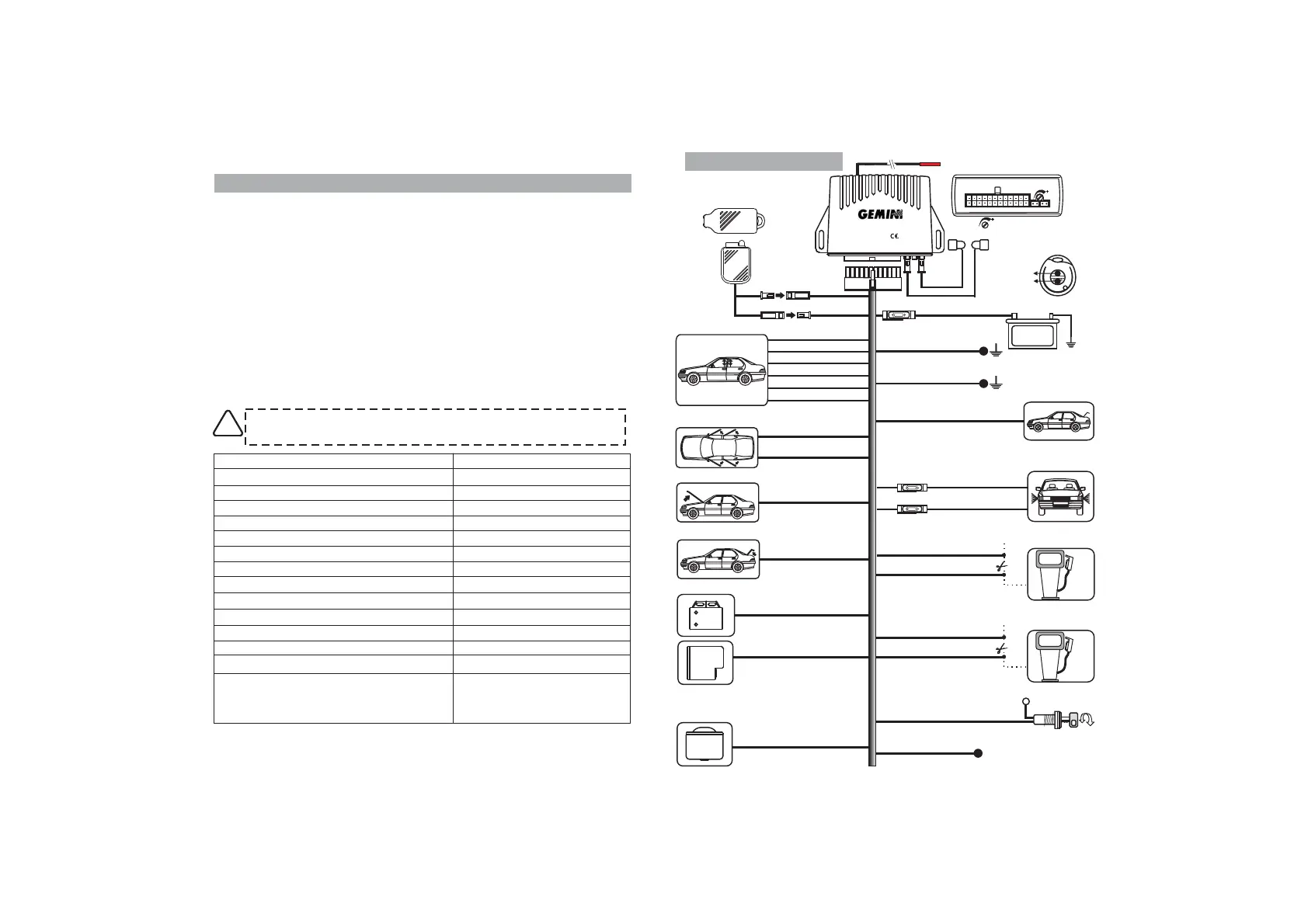
For CDL connections refer to wiring diagram.
The table below refers to the alarm wiring diagram (see opposite page).
complete all electrical connections
NB: available diagrams, for each specific vehicle, can be requested to
the zone dealer.
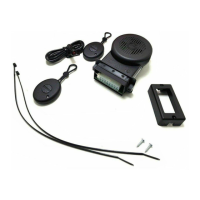
NB: The BLACK 2-pin connectors in the alarm harness are for the
electronic key and LED connections.
Negative
Positive
Engine immobilization 1
Engine immobilization 1
Ignition
Door pin switches
Bonnet/boot switches
Positive alarm ON
External sensor input
Negative control for additional siren
Self-powered siren
Turn indicators
Negative output for electric boot release
CDL (see diagram)
2
BLACK marked
BLACK wires marked
2 BLACK wires marked ‘B’
BLACK marked ‘G’
2
2 GREEN wires
PINK
GREEN/BLACK
YELLOW/BLACK
BLUE
2 ORANGE wires
GREY-BLACK
YELLOW/BLUE RED/BLUE
YELLOW/BROWN RED/BROWN
YELLOW/GREY RED/GREY
BLACK wires marked ‘M’
‘R’
2‘H’
GREEN/BROWN wires
FUNCTION WIRE COLOUR
ELECTRONIC KEY
YELLOW-GREY
BLACK marked ‘G’
+30
EARTH
EARTH
ORANGE
ORANGE
15A
+
Battery
12 VOLT
YELLOW-BLUE
YELLOW-BROWN
RED-GREY
RED-BROWN
RED-BLUE
6.0 - WIRING DIAGRAM
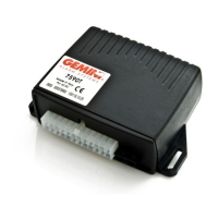
ART.7590T
Negative control for
additional siren
YELLOW-BLACK
GREY-BLACK
BLUE
Self-powered siren output
(lack of negative in alarm)
R - Positive
M - Ground
L - Blue
S - Pink
V - Bonnet switch
GREEN-BROWN
GREEN-BROWN
Door switches
See lock diagrams
Engine immobilisation 1
Engine immobilisation 2
8A
MAX !
8A
MAX !
Positive to alarm
activated (700mA max.)
GREEN
GREEN
BLACK marked ‘R’
BLACK marked ‘M’
BLACK marked ‘M’
BLACK marked ‘H’
BLACK marked ‘B’
BLACK marked ‘B’
BLACK marked ‘H’
Bonnet switch
Boot switch
5A
5A
PINK
GREEN-BLACK
External sensors input
Negative output for
electric boot release
Black
Green
Brown
TX
W
R
US adjustment
Red
ANTENNA - Do not tamper!
RX
Made in Italy
7590
ALARM SYSTEMS
Button 2
Button 1
Turn indicators
Ignition
PAGE8
PAGE9
INSTALLER MANUAL
Before carrying out electrical connections, disconnect the NEGATIVE
BATTERY TERMINAL and only reconnect after completion.
!!