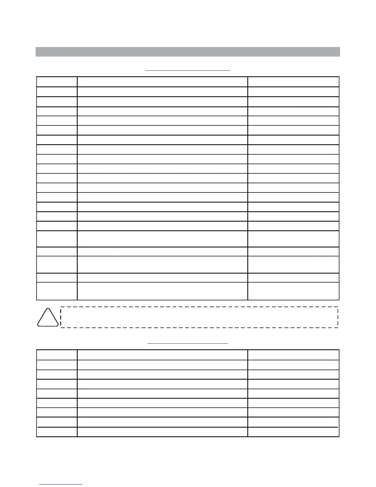
5.0 - PIN-OUT TABLES
-1-
-2-
-3-
-4-
-5-
-6-
-7-
-8-
-9-
-10-
-11-
-12-
-13-
-14-
-15-
-16-
-17-
-18-
-19-
-20-
-----
YELLOW-BLUE
GREEN-BLUE
-----
GREEN-BROWN
GREEN
BROWN
BLACK
RED
BLACK marked “G”
LIGHT BLUE-GREY
LIGHT BLUE
PINK
GREEN-BLACK
GREEN
BLUE
WHITE-BLACK
YELLOW-BLACK
-----
WHITE-ORANGE
WIRE FUNCTIONPOSITION
WIRE COLOUR
5.1 - 20-PIN CONNECTOR
INSTALLER MANUAL
WHITE-ORANGE wire must ALWAYS be connected if system arms/disarms via the turn
indicators.
!
-----
System arming signal
System disarming signal
-----
Door trigger positive/negative input
Receptacle for electronic key input
Receptacle for electronic key negative ground
LED negative output
LED positive output
Ignition
CAN BUS signal (CAN-H)
CAN BUS signal (CAN-L)
Positive output with system armed (+A)
External sensors negative input
Bonnet switch negative input
Self-powered siren (lack of negative during alarm) or
Hazard warning lights
Comfort negative output
Additional siren or vehicle horn output (negative output
during alarm)
-----
Input for self-learning and system arming/disarming via
turn indicators flashes
PAGE 06 - INSTALLER MANUAL
Ground
Siren output
Positive
Turn indicators positive output
Engine block
Siren output
Engine block
Turn indicators positive output
-1-
-2-
-3-
-4-
-5-
-6-
-7-
-8-
BLACK marked “M”
-----
BLACK marked “R”
ORANGE
BLACK marked “H”
-----
BLACK marked “H”
ORANGE
WIRE FUNCTIONPOSITION
WIRE COLOUR
5.2 - 8-PIN CONNECTOR

 Loading...