7.0-C
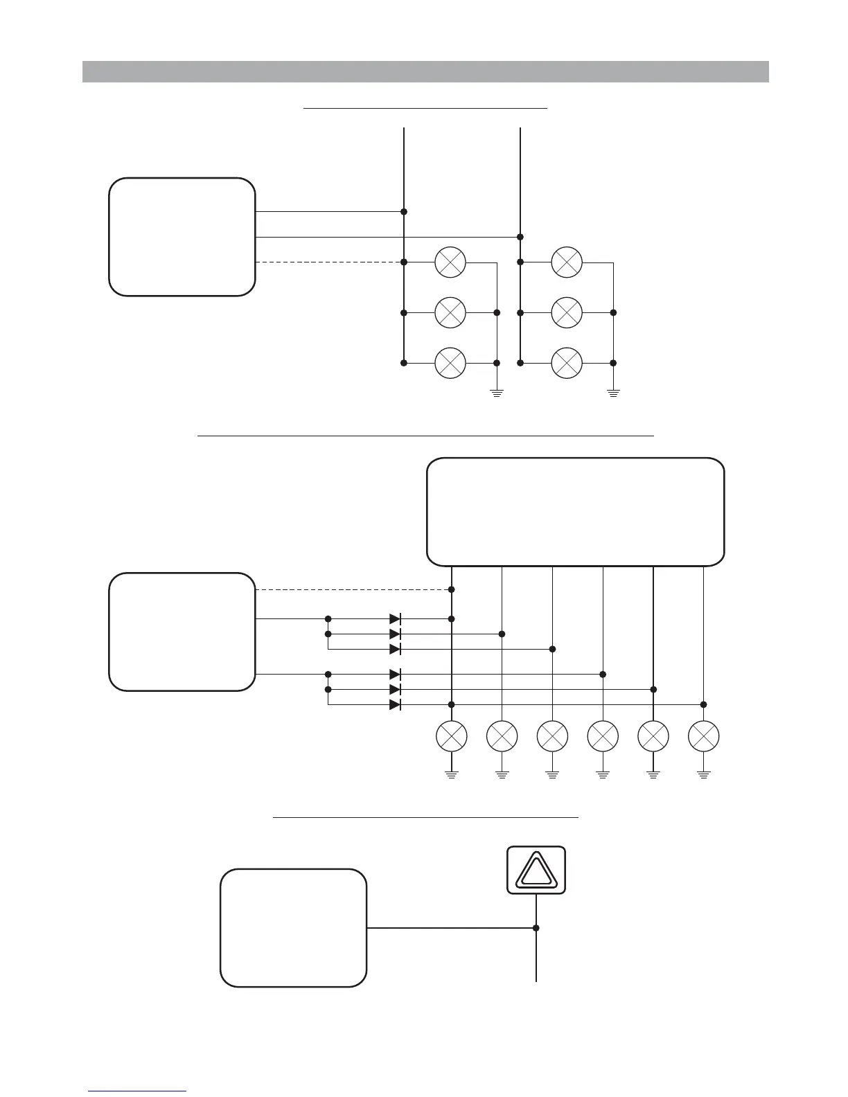
7.1 - STANDARD CONNECTIONS
ONNECTION FOR TURN SIGNALS ACTIVATION
PAGE 08 - INSTALLER MANUAL
GEMINI 933
SYSTEM
GEMINI 933
SYSTEM
GEMINI 933
SYSTEM
RIGHT TURN
INDICATORS
LEFT TURN
INDICATORS
ORANGE
WHITE-ORANGE
ORANGE
TURN INDICATORS
CONTROL UNIT
ORANGE
WHITE-ORANGE
ORANGE
7.2 - CONNECTIONS FOR VEHICLES WITH SEPARATE LINES
7.3 - CONNECTION TO HAZARD SWITCH
VEHICLE
ELECTRICAL
SYSTEM
BLUE
WHITE-ORANGE wire must ONLY be
connected if the system is to operate
through turn indicators.
WHITE-ORANGE wire must ONLY be
connected if the system is to operate
through turn indicators.
Insert nr. 6
2 Ampere
diodes.
In the “SYSTEM
PROGRAMMING” menu,
select “Hazard warning
lights” (optical pulse signals).
Do not make this connection
if the system is to operate
through turn indicators.
Front
LH
Rear
RH
Side
LH
Side
RH
Rear
LH
Front
RH

 Loading...