4.0 - PINOUT TABLES
-1-
-2-
-3-
-4-
-5-
-6-
-7-
-8-
-9-
-10-
-11-
-12-
-13-
-14-
-15-
-16-
-17-
-18-
-19-
-20-
-----
-----
-----
-----
GREEN-BROWN
GREEN
BROWN
BLACK
RED
BLACK marked “G”
LIGHT BLUE-GREY
LIGHT BLUE
PINK
GREEN-BLACK
GREEN
BLUE
WHITE-BLACK
YELLOW-BLACK
-----
-----
WIRE FUNCTIONPOSITION
WIRE COLOUR
15A
+
Battery
8A
MAX !
BLACK marked “M”
GROUND
POSITIVE
BLACK marked “R”
ORANGE**
ORANGE**
Output - turn indicators
BLACK marked “G”
+30
Ignition
BLACK marked “H”
BLACK marked “H”
Engine immobilizer
GREEN
Bonnet switch
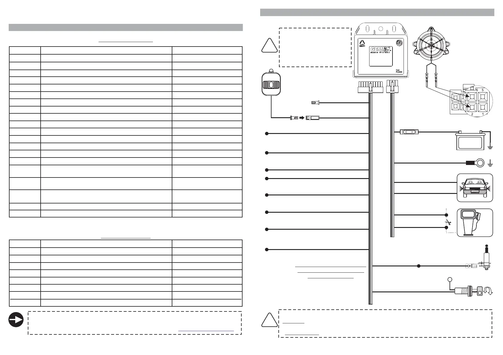
5.0 - WIRING DIAGRAM
Connection
with supplied sounder
P/N 7746
Before carrying out
electrical connections,
disconnect the negative
battery terminal and re-
connect again after
completion.
!
20-PIN CONNECTOR
1
567
234
8
INSTALLER MANUAL
-----
-----
-----
-----
Positive/negative input - door switches
DO NOT CONNECT
DO NOT CONNECT
LED negative output
LED positive output
Ignition
CAN BUS (CAN-H) signal
CAN BUS (CAN-L) signal
Positive output - system armed (+A)
Negative input - external sensors
Negative input - bonnet switch (for pairing purposes)
Optical pulse signals (Hazard)
Lock command (1.5 sec.* negative pulse when pressing
remote control button “1” or “3”)
Unlock command (1.5 sec.* negative pulse when
pressing remote control button “2”)
-----
-----
Negative input - external sensors
Positive/negative input - door switches
GREEN-BLACK
GREEN-BROWN
CAN BUS signal
LIGHT BLUE-GREY (CAN-H)
PAGE 06 - INSTALLER MANUAL INSTALLER MANUAL - PAGE 07
LIGHT BLUE (CAN-L)
Lock command (negative)
Unlock command (negative)
WHITE-BLACK
YELLOW-BLACK
Positive output - system armed (+A)
PINK
Ground
Siren output
Positive supply
Positive output - turn indicators
Engine immobilization
Siren output
Engine immobilization
Positive output - turn indicators
-1-
-2-
-3-
-4-
-5-
-6-
-7-
-8-
BLACK marked “M”
-----
BLACK marked “R”
ORANGE
BLACK marked “H”
-----
BLACK marked “H”
ORANGE
WIRE FUNCTIONPOSITION
WIRE COLOUR
8-PIN CONNECTOR
BLUE*
HAZARD
(optical pulse signals)
In this case, DO NOT connect
the alarm ORANGE wires to
the turn indicators.
For complete information regarding connections, please refer to the vehicle specific
wiring diagram.
(See available diagrams in the restricted area of our website: ).www.gemini-alarm.com
* If “ feature is enabled (par. 8.0), lock/unlock pulse time will be 0.5 sec.
instead of 1.5 sec.
Double pulse unlock”
Turn indicators connections: Select ONLY one of the following connections :
*
**
BLUE wire
ORANGE wires
:ONLY
.
:
Optical signals activated by connection to the Hazard switch will turn ON during an alarm
condition
turn indicator flashes for all optical signaling functions (factory enabled).
!
(Ground to pair devices)
Red
Black
Brown
Green
Do not connect
STATUS LED
Button function not applicable
for this product version.