17 / 48
1435
e
Pos
42: DeadBand
Positioner's dead band
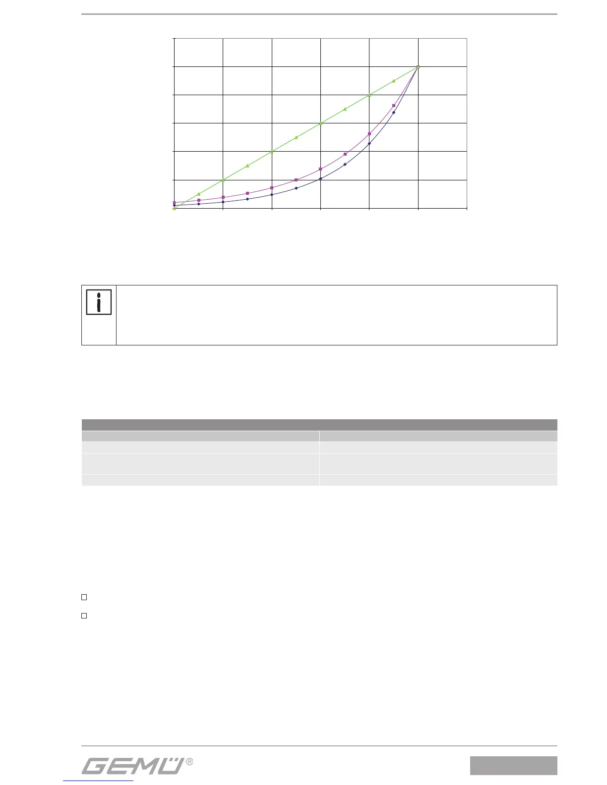
The dead band shows the maximum permissible system deviation between actual value and set value.
During initialisation, on DEADBAND = Auto the dead band is matched to the requirements of the control circuit. In the other
discrete settings the fi xed value for the dead band is used.
The height of the system deviation should always correspond to the requirements of the valve and the control circuit.
It is recommended that you do not set a value of < 1.0% since this could (especially for actuators with discontinuous
movement profiles) cause oscillating control characteristics. This could put a great deal of stress on the internal pilot
valves and cause them to reach the end of their service life more quickly.
Basically: the smaller the fixed value, the higher the wear and the shorter the service life. Therefore, the value should
be set only as accurate as needed.
43: PROP GAIN
Proportional amplifi cation
Adjusting the proportional amplifi cation Kp
Kp = 0.1...100.0
The height of the amplification should always correspond to the requirements of the valve and the control circuit. The optimum set-
ting is determined during automatic initialization but must be moved out of adjustment later if necessary.
The behaviour of the positioner is influenced as follows:
PROP GAIN
Set value larger than determined value Set value smaller than determined value
The positioner controls faster (but tends to oscillate). The positioner controls slower.
The set value is achieved in larger steps by increasing the
correcting variable.
The set value is achieved in smaller steps by decreasing the
correcting variable.
Control is less accurate. Control is more accurate.
44: DERIV TIME
Derivative action time
Adjusting the derivative action time Tv (time by which a specifi c correcting variable is reached earlier because of the D component
than with a pure P-positioner)
Tv = 0.00 s...10.00 s
46: RELEASE VXX
Status of the current software version V X.X.X.X
50: SYSTEMMODE
Selection of operator interface
CLASSIC
menu confi guration as described in chapter 7.2 System mode
ADVANCED
menu confi guration as described in chapter 7.2 System mode
In order to switch the operator interface from [CLASSIC] to [ADVANCED] proceed as follows:
1. Select parameter "50: SYSTEMMODE".
2. Switch from [CLASSIC] to[ADVANCED] and do not exit the parameter.
3. Switch off supply voltage.
4. Switch on supply voltage.
In order to switch the operator interface from [ADVANCED] to [CLASSIC] proceed as follows:
1. Select parameter "SYSTEMMODE" in the SetBasics menu.
2. Switch from [ADVANCED] to [CLASSIC] and confi rm with "OK". Do not exit the parameter.
3. Switch off supply voltage.
4. Switch on supply voltage.


 To Next Page