8 / 48
1435
e
Pos
6. Loosen screws on housing cover and swing the cover open.
7. Feed cable from linear travel sensor into the M12 cable
gland 6 of the positioner and connect to the terminal board
as shown in the wiring diagram (see chapter 6).
8. Then tighten the M12 gland. The cable must be held fi rmly
on all sides.
4.3 Remote mounting
1. The actuator must be in the zero position (actuator vented).
2. Mount travel sensor as described in chapter 4.1 or 4.2.
3. Feed travel sensor cable into the M12 cable gland of the
positioner and connect to the terminal board as shown in
the wiring diagram (see chapter 6).
4. Then tighten the M12 gland. The cable must be held fi rmly
on all sides.
5 Pneumatic connections
Filter strainers are installed in the pneumatic
connectors of the positioner to protect against
rough dirt particles. They can be ordered as
spare parts with order number 1435 SFI. Each
kit contains 3 filter strainers. These filter strainers
are meant as an additional protection and do not
replace the requirement to filter all site compressed
air.
1. Make the connection between pneumatic positioner out-
let A1 (single acting) or A1 and A2 (double acting) and the
pneumatic actuator control air inlet.
2. Connect the control air supply (additional air) to the air sup-
ply connection P* (max. 6 bar or 90 psi).
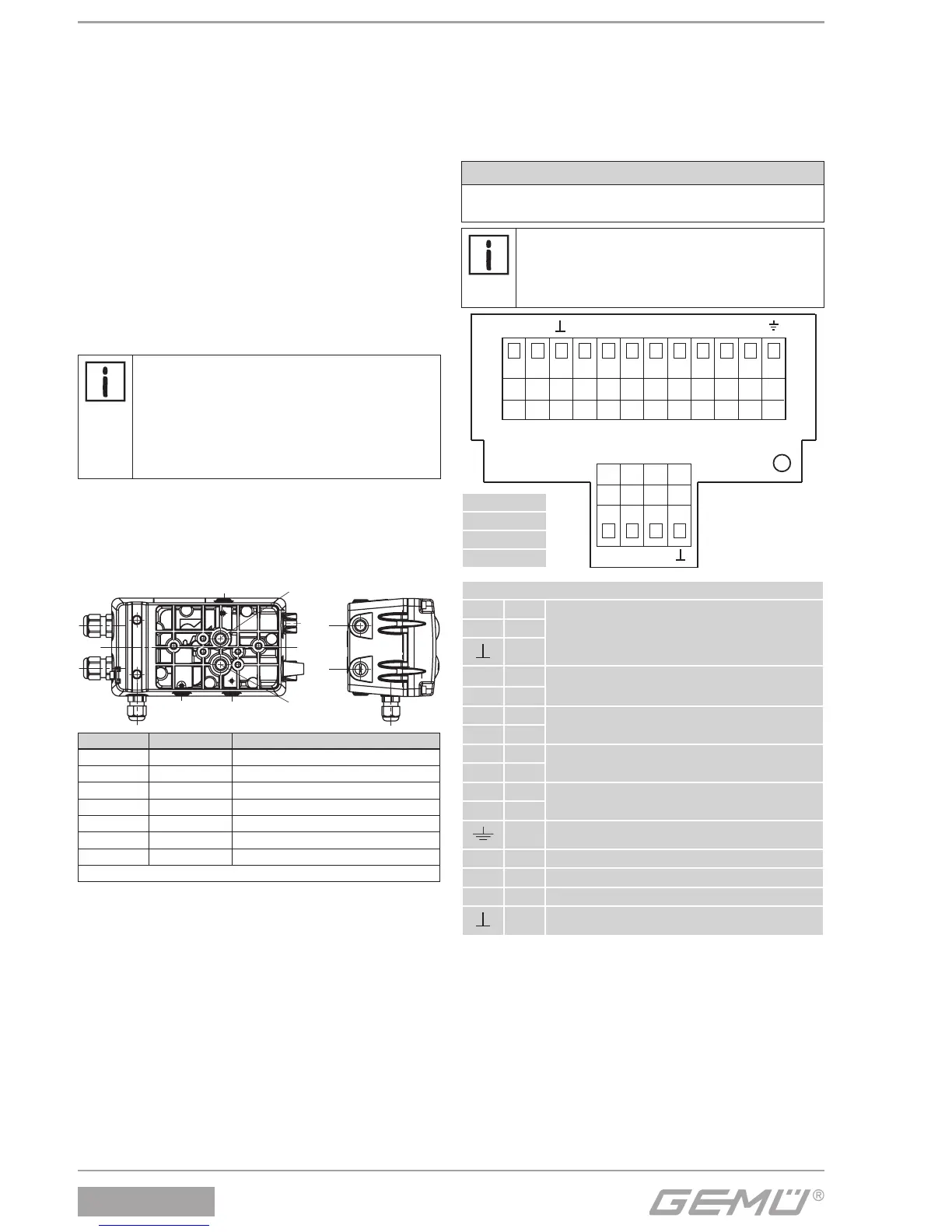
Connection DIN ISO 1219-1 Description
P 1 Air supply connection G1/4
R 3 Venting connection G1/4 with silencer
D1 V1 Exhaust air throttle for A1
D2 V2 Exhaust air throttle for A2*
RV V3 Non-return valve
A1 2 Working connection for process valve
A2 4 Working connection for process valve*
* only double acting type (code 3)
5.1 Replacing the fi lter strainers
1. Switch off pneumatic control air supply.
2. Remove connection lines.
3. Carefully remove fi lter strainers from holes P, A1 and A2
(only double acting version).
4. Replace fi lter strainers (1435 SFI).
5. Re-connect connection lines.
6. Supply pneumatic control air.
6 Electrical connections
6.1 Version with terminals (standard)
1. Connect travel sensor (if not already done).
2. Connect analogue input 0/4-20 mA or 0-10 V to the
appropriate terminals for specifi cation of set values.
3. Connect 24 V DC supply voltage cable and potential earth.
CAUTION
Damage to the spindle surface may lead to failure of the
travel sensor!
Important:
In order to compensate for differences of earthing
potential due to plant-specific installations, a
jumper can be placed between terminals "GND"
and "I
w
-".
10 V X U
W
+ I
W
+ I
W
- U
W
- X+ X-
GND 24 V
or or or gr gr gr gr gr gr bl bl gn
gr gr gr gr
A1 A2
ERR
or orange
gn green
bl blue
gr grey
Legend
10 V green
Connection of external travel sensor
X brown
white
I
w
+
Set value input 0/4-20 mA
I
w
-
U
w
+
Set value input 0-10 V
U
w
-
X+
Actual value output 0-10 V
4-20 mA (optional) - internal supply
X-
GND
Supply voltage 24 V DC
24 V
Potential earth
A1 Alarm1, 24 V DC
A2 Alarm2, 24 V DC
ERR Error message output
GND out


 To Next Page