7 / 48
1435
e
Pos
4 Mechanical mounting
When operating with an actuator of control function
2 (opened by sping force), fi t an external throttle
(order number 1435 DR6Z) into the air supply line
(connection P).
4.1 Mounting to linear actuators
4.1.1 Preparation of the actuator
1. The actuator must be in the zero position (actuator vented).
2. Should there be an optical position indicator in the actuator
(a red spindle), it must be removed.
3. Should there be a thread cover in the top of the actuator,
remove this too.
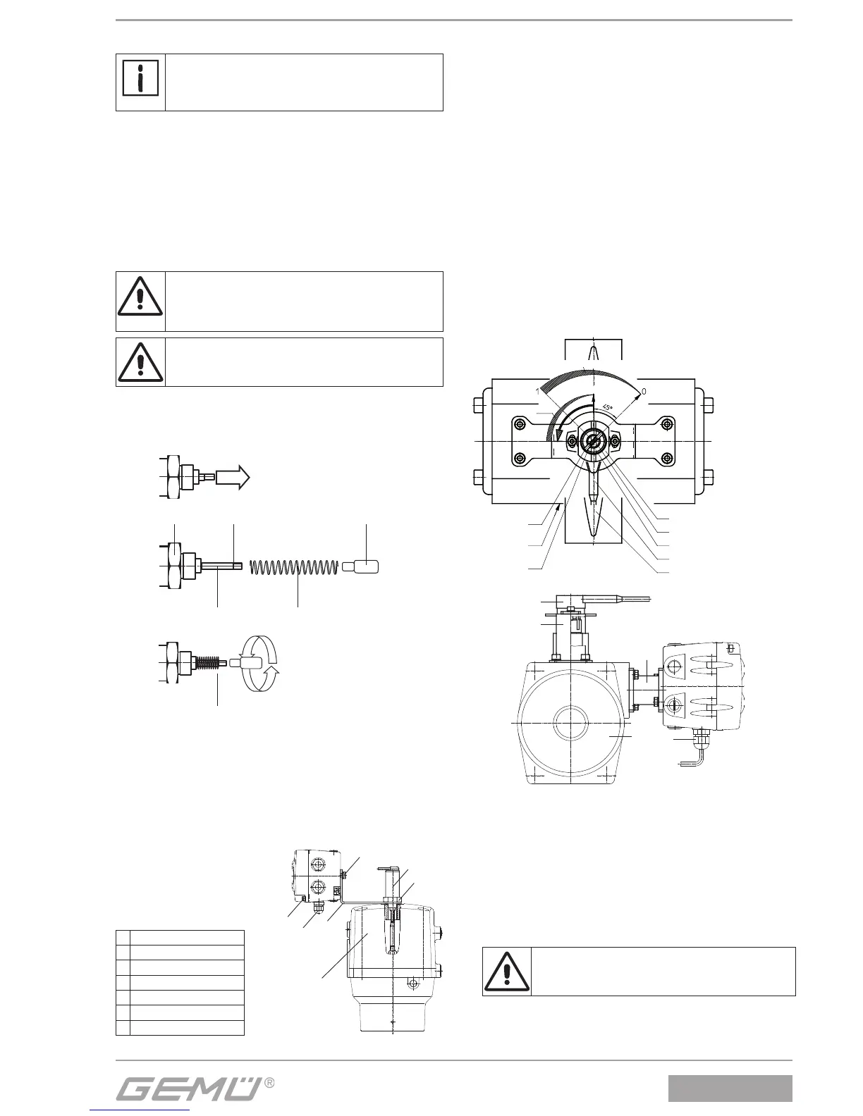
4.1.2 Assembling the travel sensor
DANGER
Pretensioned spring!
ä Damage to the device.
● Slowly relax spring.
Attention: Damage to the spindle surface may lead
to failure of the travel sensor!
In the standard version the travel sensor consists of the travel
sensor, a compression spring and an operating bush (on larger
actuators a guide bush is also supplied which is fi tted behind
the compression spring).
Travel sensor a
a
Spindle Spring
Operating bush
1. Pull out the spindle of the travel sensor up to the limit stop.
2. Push the spring over the spindle.
3. Fix the spindle at point a
(the spindle must not be damaged during this pro-
cess).
4. Screw the operating bush onto the spindle.
4.1.3 Mounting the positioner
1 Mounting bracket
2 Actuator
3 Travel sensor
4 Hexagon
5 M6 screws
6 M12 cable gland
7 M4 screws
7
2
4
3
5
6
1
1. For control function 1 (normally closed) place the mounting
bracket 1 between the actuator head 2 and travel sensor 3
and fi x by turning the travel sensor at the hexagon 4.
2. For control function 2 (normally open) and control func-
tion 3 (double acting) place the mounting bracket 1
between the threaded adapter and travel sensor 3 and also
place a sealing ring there. Fix by turning the travel sensor at
the hexagon 4.
3. Attach the positioner to the mounting bracket 1 with 2 M6
screws 5.
4. Loosen screws 7 on housing cover and swing the cover
open.
5. Feed cable from linear travel sensor into the M12 cable
gland 6 of the positioner and connect to the terminal board
as shown in the wiring diagram (see chapter 6).
6. Then tighten the M12 gland. The cable must be held fi rmly
on all sides.
4.2 Mounting to quarter turn actuators
4.2.1 Preparation of the actuator
Actuator shaft (from above)
Rotary potentiometer shaft
Adapter
Rotary potentiometer connection
Butterfly disc: closed
Adapter marking
Pneumatic
connection
Potentiometer
shaft marking
Rotary potentiometer
Actuator
Butterfly
valve: open
Butterfly
valve: closed
3
1
6
2
4
1. The actuator must be in the zero position (actuator vented).
Double acting actuators should be moved to the valve
"CLOSED" position.
2. Remove the screw which retains the optical position indica-
tor.
3. Determine the turn direction of the actuator (seen from
above the turn direction of the actuator must be anticlock-
wise, when the actuator moves from the "CLOSED" to the
"OPEN" position).
4. Bolt rotary travel sensor 3 to the actuator with mounting
bracket 1.
Observe correct fi tting position of rotary travel
sensor to "double fl ats".
5. Mount positioner directly on the quarter turn actuator 2 us-
ing a NAMUR adapter 4.