Section 6: Electrical Connections
Installation Guidelines For 60 Hz Air-cooled Generators 23
Section 6: Electrical Connections
Generator Connections
NOTE: Control wiring may be already wired on pre-wired
generators. If so, tighten the 5 foot (1.5 meter) whip
conduit inside of the enclosure. If not, wiring must be in
accordance with local jurisdiction and codes.
1. Remove the appropriate main AC/control wiring
knock-out plug from the back of the generator.
2. Install the conduit and main AC and control wires
between the generator and the transfer switch. See
Figure 2-6 for knockout locations (verify specific
transfer switch wiring/connections per model).
NOTE: These wiring connections may be present on
pre-wired models.
NOTE: This wiring can be run in the same conduit if the
appropriate insulation rated wire is used, or if the
provided sleeve is used to separate the high and low
voltage control wires.
3. Seal the conduit at the generator and in
compliance with any codes.
4. Strip the insulation from the ends of the wires. Do
not remove excessive insulation.
5. To connect the control wires, push down on the
spring loaded connection point with a flat head
screwdriver, insert wire and release.
NOTE: No wire insulation should be in the connection
point, only bare wire.
Control Wiring
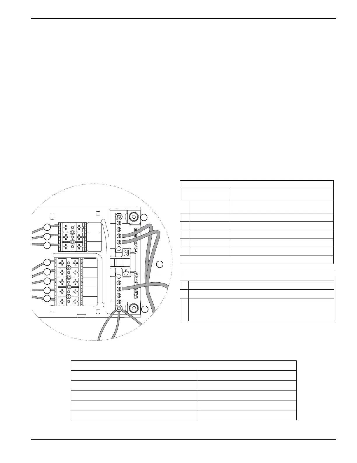
Figure 6-1. Control Wiring Connections
SENSE
N1
UTILITY
209
COMMOM
ALARM
210
COMMON
ALARM
0
DC COMMON
194
+12 VDC
23
TRANSFER
T1
VAC LOAD
SUPPLY
N2
UTILITY
000914
A
A
C
D
E
F
B
F
Table 6-1. Control Panel Connections
Terminal Numbering
Decal
Wire Numbers
A YELLOW #1 & #2
N1 & N2 - 240 VAC - Sensing for Utility Dropout and
Pickup
B* BLUE #3 T1 - Fused 120 VAC for Battery Charger (*see NOTE)
C BLACK #3 0 - DC (-) Common Ground Wire
D RED #4 194 - DC (+) 12 VDC for Transfer Controls
E WHITE #5 23 - Transfer Control Signal Wire
F BLUE #1 & #2 Optional Alarm Relay Contacts (Normally Open)
Note: Must be connected to keep battery charged whether unit is running or not.
Table 6-2. Ground and Neutral Connections
1 Large Neutral Lug Torque Spec 2/0 TO 14 AWG 120 in-lb (13.56 N-m)
2 Large Ground Lug Torque Spec 2/0 TO 14 AWG 120 in-lb (13.56 N-m)
3
Ground and Neutral Bus Bar Torque Specs:
4-6 AWG 35 in-lb (3.95 N-m)
8 AWG 25 in-lb (2.82 N-m)
10-14 AWG 20 in-lb (2.26 N-m)
1
2
3
Table 6-3. Control Wire Recommended Length and Size
Maximum Wire Length Recommended Wire Size
1-115 ft (1-35 m) No. 18 AWG
116-185 ft (36-56 m) No. 16 AWG
186-295 ft (57-89 m) No. 14 AWG
296-460 ft (90-140 m) No. 12 AWG
 Loading...