Section 6: Electrical Connections
24 Installation Guidelines For 60 Hz Air-cooled Generators
Main AC Wiring
NOTE: Main AC wiring must be in accordance with local
jurisdiction and codes.
1. Strip the insulation off the wire ends. Do not
remove excessive insulation.
2. Remove the two cap plugs located behind the
breaker door and to the right of the Main Breaker.
3. Loosen the lugs of the Main Breaker through the
access holes.
4. Insert a power wire (E1 or E2) through the opening
in the back cover and into the bottom lug. Torque to
the proper specification.
NOTE: There are 3 screws inside the top of the breaker
panel (behind the breaker door). Removing these screws
will allow the entire breaker box to be carefully pulled out.
When reinstalling, be certain that the tabs on the bottom
lock into place.
5. Connect the Neutral wire to the Neutral Lug if
applicable. Torque to the required specification.
See Table 6-2.
6. Connect the Ground wire to the Ground Lug and
torque to the required specification. See Table 6-2.
NOTE: Neutral Bonding - For installations that require
the neutral to be bonded to the ground, this is to be done
on the customer connections terminals inside the
generator. Connect a suitably sized wire from the neutral
bar to the ground bar. This is normally required when the
generator is the source in a separately derived system. It
is not required when the generator is a backup source in
a utility supplied electrical system with a 2-pole transfer
switch. See Figure 6-1.
NOTE: Torque all wiring lugs, bus bars and connection
points to the proper torque specifications. Torque
specifications for the Main Line Circuit Breaker (MLCB)
can be found on a decal located on the inside of the Main
Line Circuit Breaker Door.
Battery Requirements
Group 26R, 12V, 540CCA (Minimum CCA)
Battery Installation
Fill the battery with the proper electrolyte fluid if
necessary and have the battery fully charged before
installing it.
Before installing and connecting the battery, complete the
following steps:
1. Verify that the generator has been turned OFF.
2. Turn off utility power supply to the transfer switch.
3. Remove the 7.5A fuse from the generator control
panel.
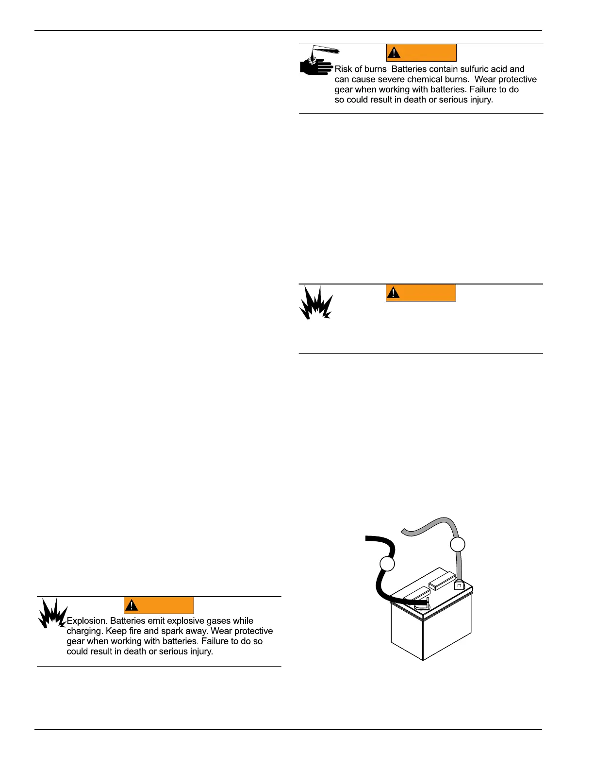
Battery cables were factory connected at the generator.
See Figure 6-2. Connect cables to battery posts as
follows:
4. Connect the red battery cable (from starter
contactor) to the battery post indicated by a
positive, POS or (+).
5. Connect the black battery cable (from frame
ground) to the battery post indicated by a negative,
NEG or (-).
6. Install the red battery post cover (included).
NOTE: Dielectric grease should be used on battery
posts to aid in the prevention of corrosion.
NOTE: Damage will result if battery connections are
made in reverse.
Figure 6-2. Battery Cable Connections
(000133)
WARNING
Explosion. Batteries emit explosive gases.
Always connect positive battery cable first to
avoid spark. Failure to do so could result in
death or serious injury.
A
B
A. Negative (-) Black lead from frame
B. Positive (+) Red lead from starter contactor