Section 2: Unpacking and Inspection
Installation Guidelines For 60 Hz Air-cooled Generators 9
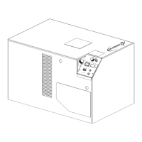
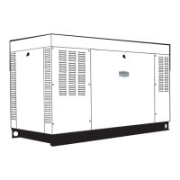
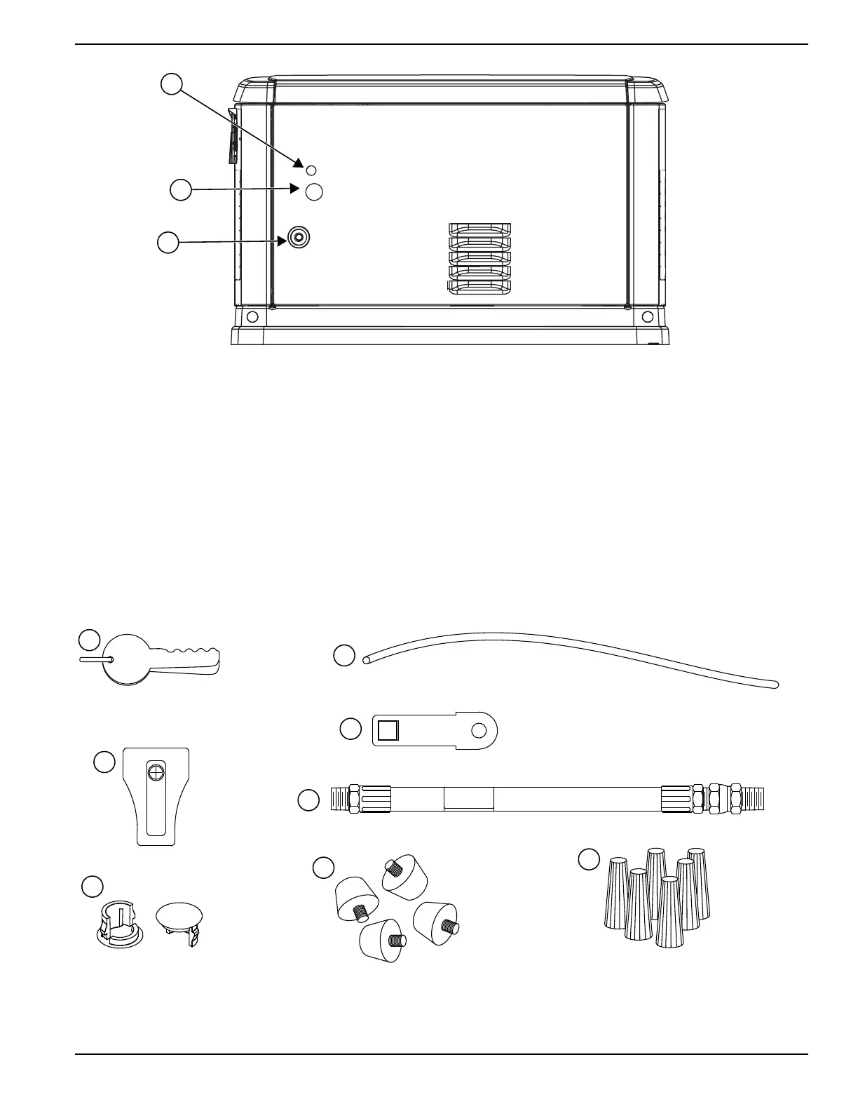
Figure 2-6. Rear of Generator
Parts Shipped Loose
1. Keys
2. Battery Terminal Cap
3. Main Line Circuit Breaker (MLCB) Terminal Caps
4. Wire Shielding to separate AC from DC control
wires
5. Main Line Circuit Breaker (MLCB) Locking
Mechanism
6. Flexible Fuel Line
7. Rubber Mounts (only for units that include fascia)
8. Wire Nuts (for pre-wired switches only)
9. Installation and Owner’s Manuals (not shown)
Figure 2-7. Parts Shipped Loose
A
C
A. Main AC/Control Wiring hole for 3/4 inch conduit
B.Main AC/Control Wiring hole for 1-1/4 inch conduit
C. Fuel Connection Hole
B
 Loading...