General Information
Synergy Automatic Standby Generator Owner’s Manual 7
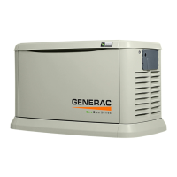
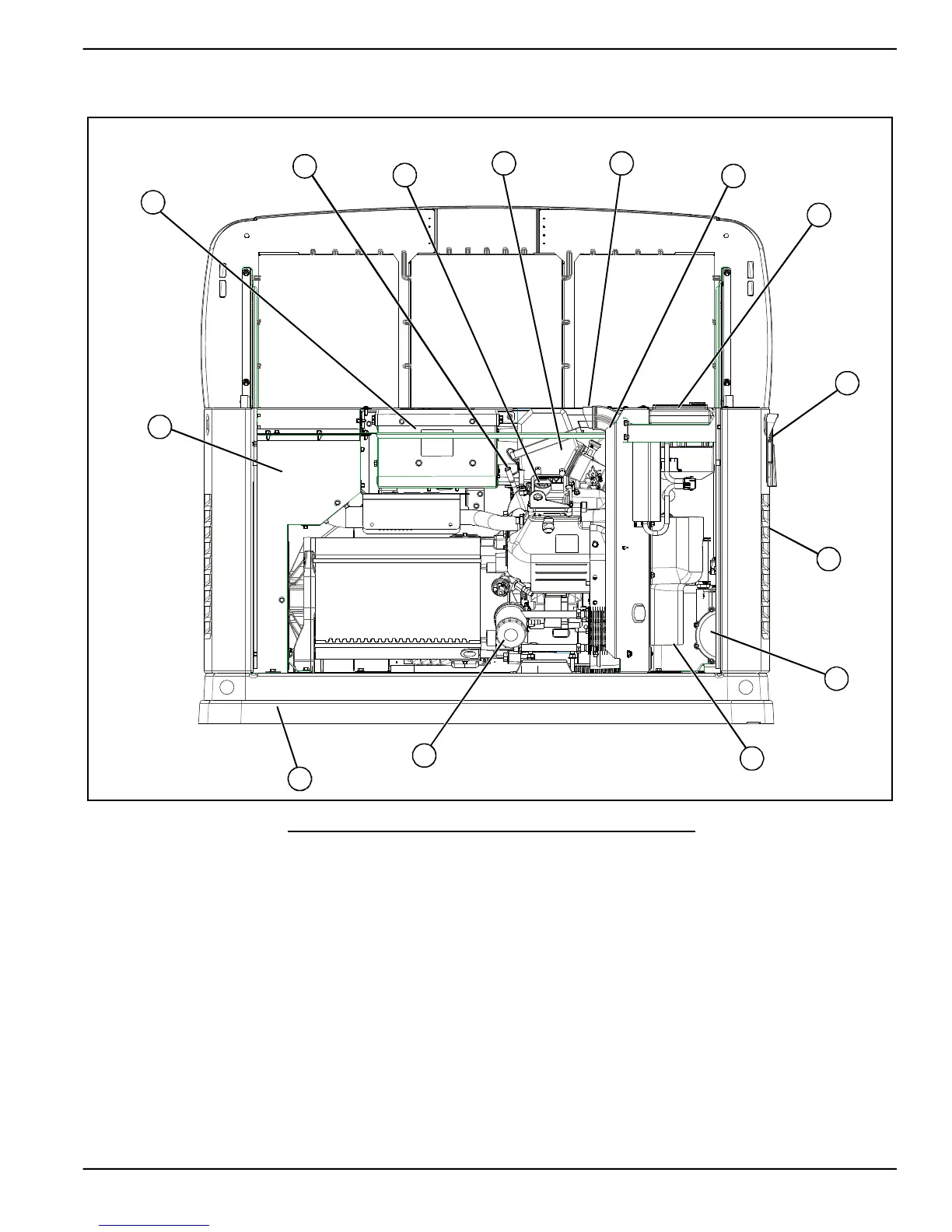
2.2 — The Generator
Figure 2-1. Component Locations
A. Automatic Voltage Regulator (AVR) H. Circuit Breakers
B. Oil Dipstick I. Fuel Inlet (Back)
C. Oil Fill Cap J. Fuel Regulator
D. Engine Air Filter K. Battery Compartment
E. AVR Air Filter L. Oil Filter
F. Data Label M. Composite Base
G. Control Pad N. Exhaust Enclosure
A
B
C
D E
F
G
H
I
J
K
L
M
N