Controller Operation
Engine Aftertreatment Monitoring
This section describes the indicators that display on the
After Treatment Status page of the Engine tab.
To access the After Treatment Status status page:
1. Press an arrow button (▲, ►, ▼, or ◄) to access
the Maintenance pages.
2. When on the Engine tab, press ▼ to scroll through
the pages until the After Treatment Status page
displays.
Four areas of the After Treatment Status page communi-
cate information to the operator. The areas and the indi-
cators that appear in those areas are explained here:
• HEST Lamp (High Exhaust System Tempera-
ture): This area displays the regeneration under-
way indicator above the words HEST LAMP -
SOLID when the unit is in the process of the ex-
haust catalyst. During the regeneration process,
the exhaust temperature will be very high.
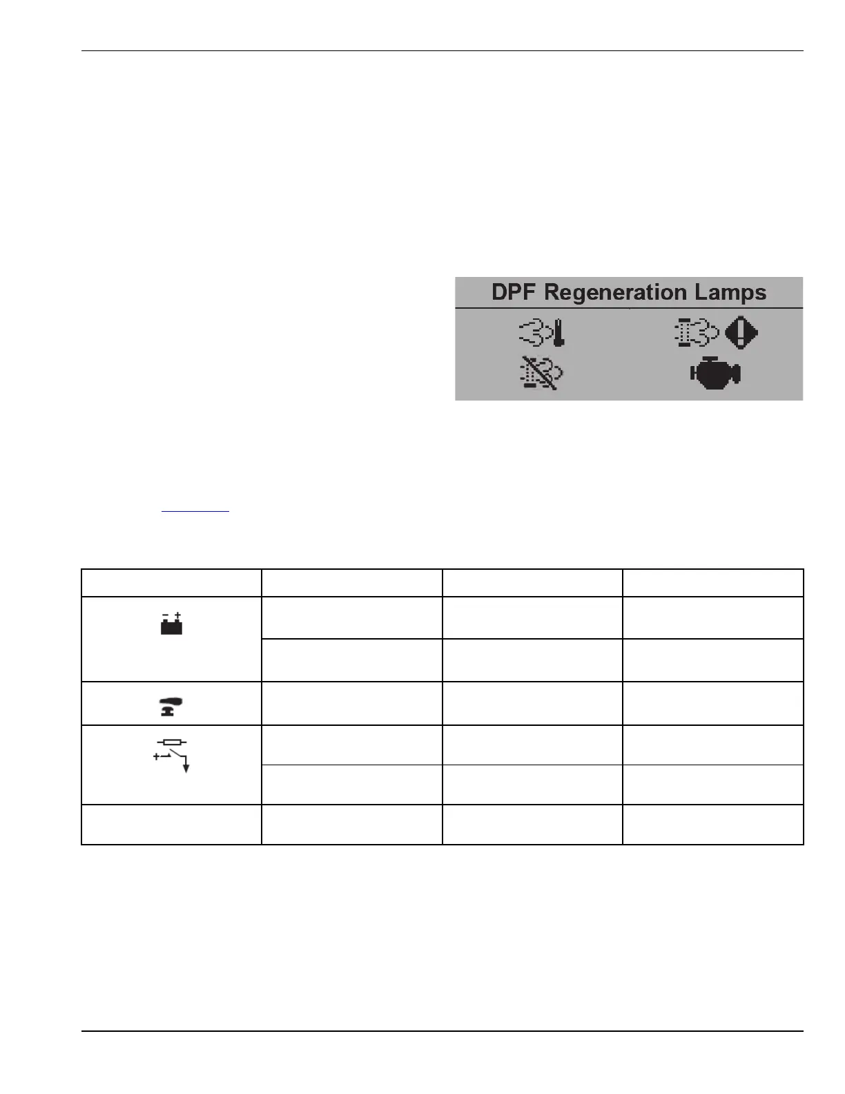
• DPF Regeneration Lamps: Depending upon the
Engine Type selected in the module’s configura-
tion, the Engine section may include the DPF
Regeneration Lamps page. This page contains
icons to show the status of various ECU functions,
some of which are applicable to Tier 4 engine re-
quirements. The icons flash at different rates to
show the status of the ECU function, refer to the
engine manufacturer for more information about
this.
• Diagnostic Codes & Events: This area will display
the engine alarm indicator above the words ALARM
- SOLID when an alarm condition occurs. This area
displays different text depending upon which alarm
condition occurs.
Figure3-6.
Figure 3-6. DPF Regeneration Lamps
Pin Map
NOTE: See Table 3-2 to aid user connection, icons are used on the rear of the module to help identify terminal
functions.
Table 3-2. Pin Map
Pin Cable Size Description
1 2.5 mm²
AWG 13
DC Plant Supply Input
(Negative)
2 2.5 mm²
AWG 13
DC Plant Supply Input
(Positive)
3 2.5 mm²
AWG 13
Emergency Stop Input
4 2.5 mm²
AWG 13
DC Output A (FUEL)
5 2.5 mm²
AWG 13
DC Output B (START)
D+
W/L
6 2.5 mm²
AWG 13
Charge Fail / Excite
Deep Sea Electronics® G8601 Controller Owner’s Manual 25