Automatic Transfer Switch Owner’s Manual 13
Section 4 Operation
4.1 — Functional Tests and Adjust-
ments
Following transfer switch installation and interconnection,
inspect the entire installation carefully. A competent,
qualified electrician should inspect it. The installation
should comply strictly with all applicable codes, stan-
dards, and regulations. When absolutely certain the
installation is proper and correct, complete a functional
test of the system. Perform functional tests in the exact
order presented in this manual, or damage to the switch
could result.
IMPORTANT: Before proceeding with functional tests, ver-
ify the instructions and information in this section is under-
stood. Also read the information and instructions of labels
and decals affixed to the switch. Note any options or
accessories that might be installed and review their opera-
tion. Confirm that there is no debris present in and/or
around the switch mechanism from the installation.
4.2 — Manual Operation
A manual switch handle is shipped with the transfer
switch. Manual operation must be checked before the
transfer switch is operated electrically. To check manual
operation, proceed as follows:
1. In the transfer switch enclosure, set the Mainte-
nance Disconnect switch to manual. This prevents
the generator from starting automatically as soon
as the utility power source is turned OFF.
2. If so equipped, turn the generator’s AUTO/OFF/
MANUAL switch to OFF.
3. Turn OFF both normal and standby power supplies
to the transfer switch, with whatever means pro-
vided, such as the main line circuit breaker(s).
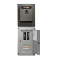
4. Note position of transfer mechanism main contacts
by observing display windows in “A” and “B” in Fig-
ure 4-1 as follows:
• Window (A) ON, Window “B” OFF - load terminals
(T1, T2, T3) are connected to normal terminals
(N1, N2, N3).
• Window (A) OFF, Window “B” ON - load terminals
(T1, T2, T3) are connected to standby terminals
(E1, E2, E3).
Figure 4-1. Main Contacts
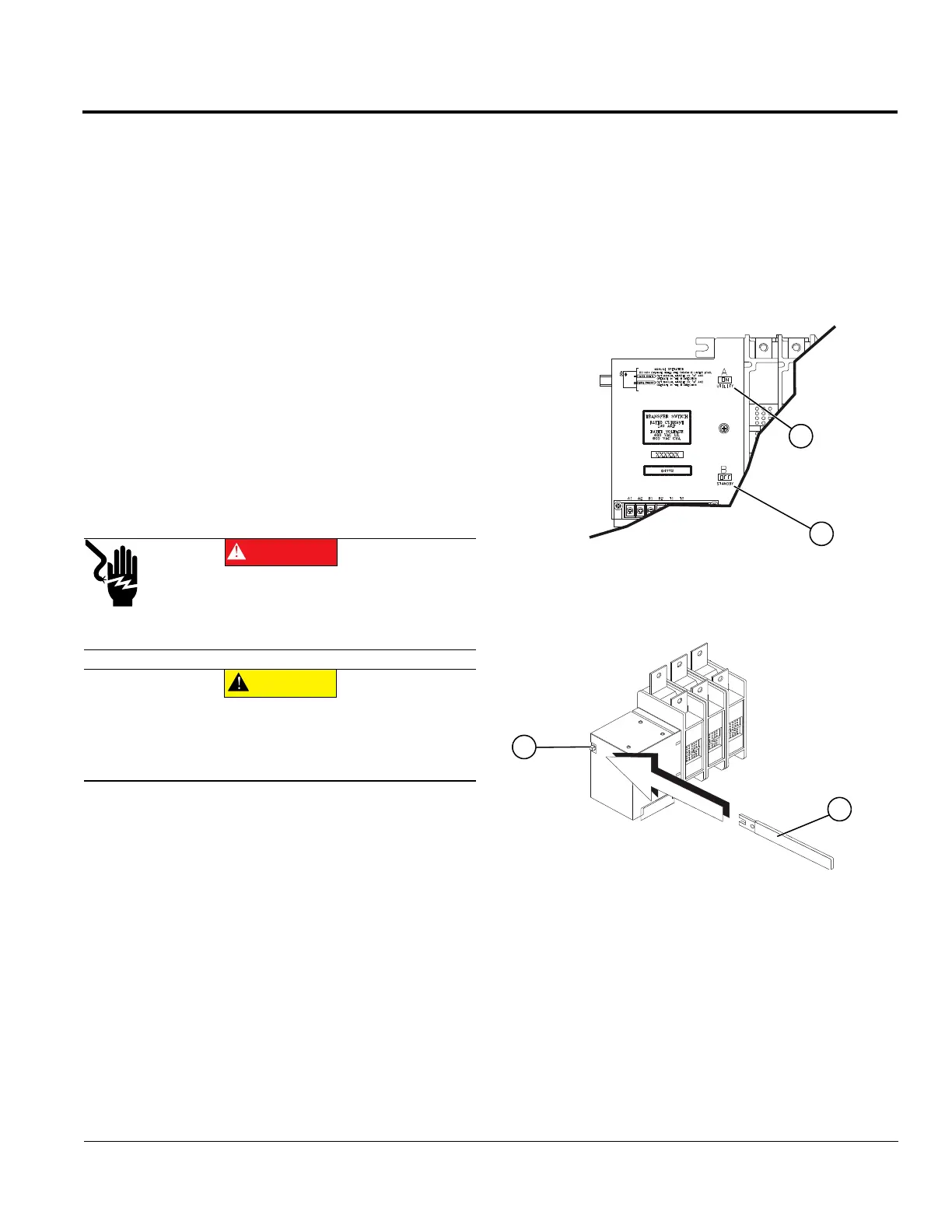
5. See Figure 4-2. Attach handle (A) to actuating
shaft (B).
Figure 4-2. Attach Handle to Actuating Shaft
6. Move handle down, then release slowly to allow
internal spring to relax.
'$1*(5
&MFDUSPDVUJPO%POPUNBOVBMMZUSBOTGFSVOEFSMPBE
%JTDPOOFDUUSBOTGFSTXJUDIGSPNBMMQPXFSTPVSDFT
QSJPSUPNBOVBMUSBOTGFS'BJMVSFUPEPTPXJMMSFTVMU
JOEFBUIPSTFSJPVTJOKVSZBOEFRVJQNFOUEBNBHF
&$87,21
&RVJQNFOUEBNBHF%POPUVTFFYDFTTJWFGPSDFXIFO
NBOVBMMZPQFSBUJOHUIFUSBOTGFSTXJUDI%PJOHTPDPVME
SFTVMUJOEBNBHFUPUIFTXJUDIIBOEMF