Owner’s Manual for Generac PWRcell Inverter 7
General Information
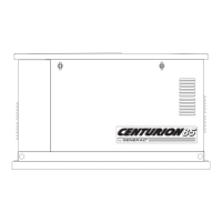
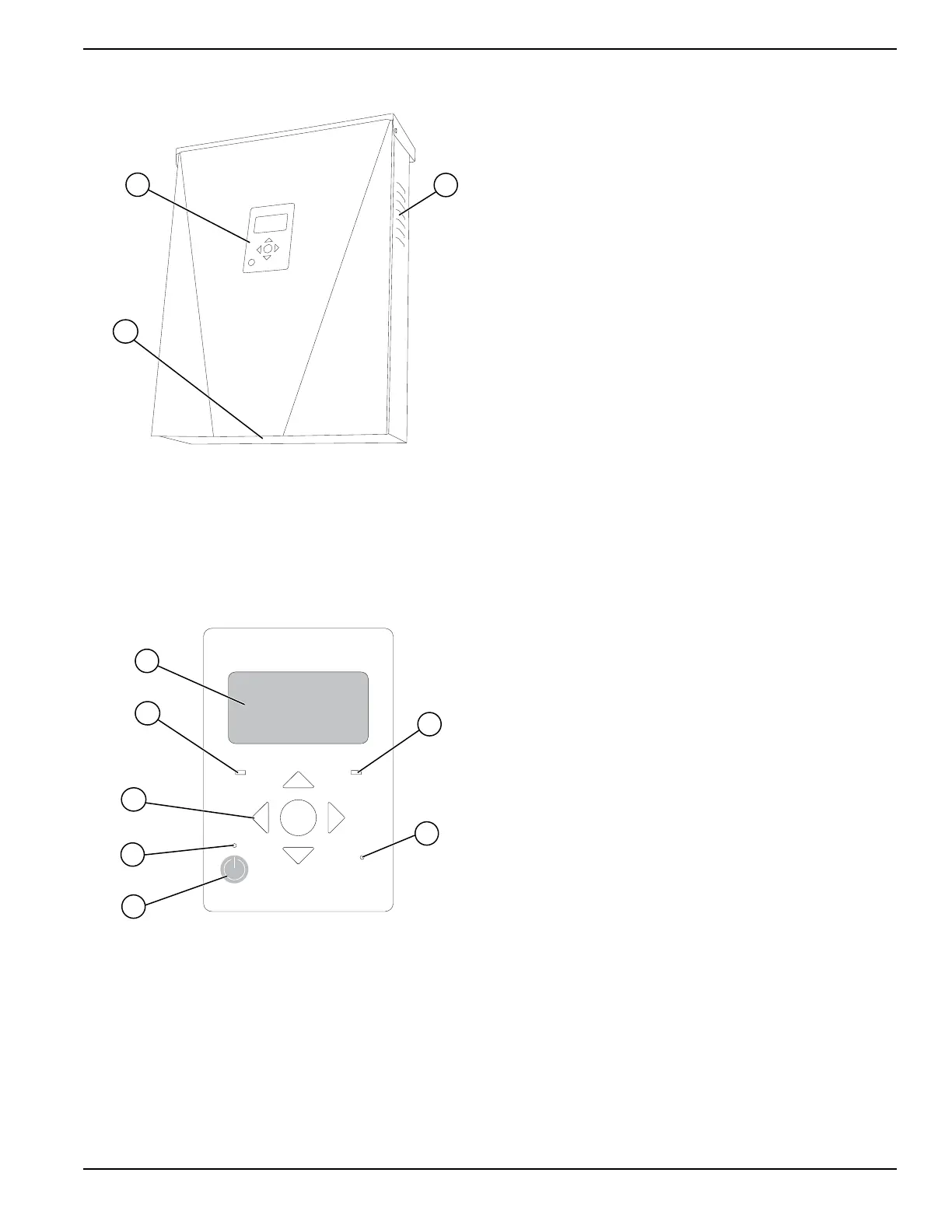
Component Locations
009656
A
B
C
Figure 2-4. Component Locations
A Control panel
B Intake filter
C Exhaust vent
Inverter Control Panel
REbus Inverter
Internet
Shutdown
(hold)
009894
A
D
C
B
G
E
F
Figure 2-5. Inverter Control Panel
A LCD display
B Navigation keys
C REbus status LED
D Inverter LED
E Safety Shutdown
F Safety Shutdown LED
G Internet LED
See Figure 2-5. Generac PWRcell is controlled through
the Generac PWRcell Inverter control panel. The inverter
control panel is used for adjusting system settings and for
interacting with devices.
LED Indicators
See Figure 2-5 for LED locations.
REbus Status LED
REbus Status LED (C) communicates REbus nanogrid
status through LED color.
• Green – all devices are functioning normally and
are either generating power or ready to generate
power.
• Yellow – no devices are connected or no devices
are enabled.
• Red – one or more REbus device has a fault that
requires attention before operation will continue.
NOTE: A red LED can also indicate a fault with the
REbus nanogrid itself. See display (A) for more
information about the specific fault detected.
Inverter LED
Inverter LED (D) communicates the status of the utility
grid and/or inverter through LED color and state.
• Green – utility is connected and within normal
operational voltage and frequency.
• Blinking green – system is in standby mode,
powering up, or initializing.
• Yellow – utility grid is not within normal conditions,
but user intervention typically is not required. The
inverter will restart as soon as the utility grid
returns to normal conditions.
• Red – a serious fault with the utility grid or inverter
has been detected and user attention is required
before the unit will resume operation. See display
(A) for more information about the specific fault
detected.
• No light – the inverter is disabled or powered off.
Safety Shutdown LED
Safety Shutdown LED (F) is illuminated when the system
is in Safety Shutdown mode. Safety Shutdown may be
initiated either from the Safety Shutdown button on the
unit or an externally-installed shutdown switch. See
Safety Shutdown.
Internet LED
Internet LED (D) is illuminated when the inverter is
connected to a router and has an IP address. See
Ethernet Configuration.
NOTE: A blue Internet LED does not mean that the
inverter has connected with the Generac server.
 Loading...