Operation
Owner’s Manual for Generac PWRCell Inverter 11
Section 3: Operation
Operation and User Interface
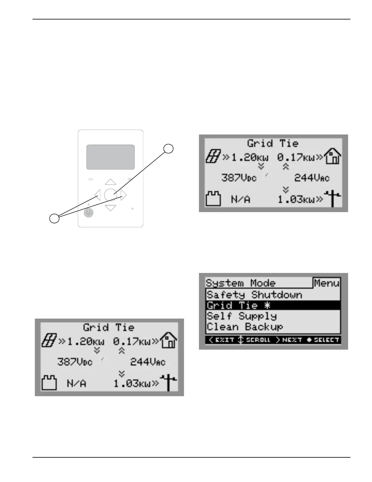
See Figure 3-1. Generac PWRcell is controlled through
the Generac PWRcell Inverter control panel. The inverter
control panel is used for adjusting system settings and for
interacting with devices.
• Use left and right arrows (A) to navigate between
pages.
• Press center button (B) from a device page to
modify device settings.
REbus Inverter
Internet
Shutdown
(hold)
009894
B
A
Figure 3-1. Inverter Control Panel
Home Screen
See Figure 3-2. The power flow display on the home
screen illustrates the flow of power in the Generac
PWRcell system. As power is generated, stored and
consumed, animated arrows indicate the flow and
direction of power. System AC and DC voltage levels are
displayed near the center of the screen. The current
operational mode is displayed at the top of the screen.
009965
Figure 3-2. Home Screen
Selecting Operational Modes
Once a system is installed, an operational mode that best
suits the user’s needs must be set. Once set, the system
remains in that mode without needing to be changed.
NOTE: An operational mode can be changed at any
time.
To select an operational mode:
1. See Figure 3-3. While viewing the home screen
press the center button.
009965
Figure 3-3. Selecting Operational Modes (1 of 4)
2. See Figure 3-4. A list of operational modes will be
displayed with the current mode marked with an
asterisk.
NOTE: The list of modes may not include all those
shown in Figure 3-4.
009966
Figure 3-4. Selecting Operational Modes (2 of 4)
 Loading...