11
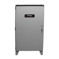
• EXERCISING: The Exercising indicator is green when the engine
generator is running an exercise cycle.
Pushbutton Arrow
When pressed the HMI screen will change to display the
Configuration Menu.
Figure 10 - Home Screen
3.10.2 CONFIGURATION MENU
The configuration menu screen is used to select and transition to
the other screens of the HMI display. To select the desired screen
press the button to the left of the description (Figure 11).
The software version numbers are also displayed at the bottom of
the screen.
The home button, in the lower right corner of the screen is used to
return to the Home Screen.
Figure 11 - Configuration Menu
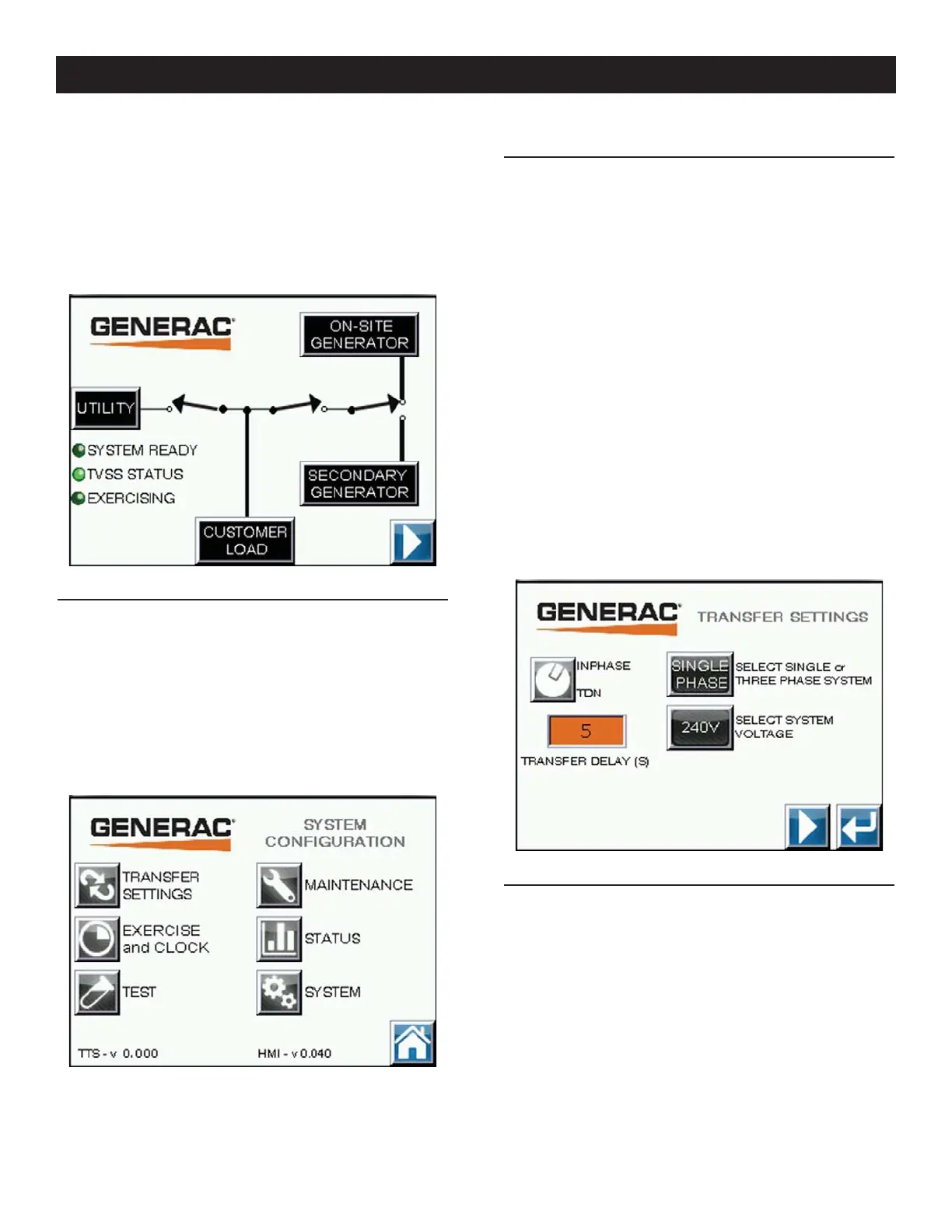
3.10.3 TRANSFER SWITCH SETTINGS #1
The Transfer Switch settings are divided into three screens. The
second screen can be accessed by pressing the “right” arrow but-
ton. To return to the System Configuration menu screen press the
return arrow (Figure 12).
Inphase or TDN - The Inphase or TDN selection is made by press-
ing the button next to it. The selection toggles with each press of
the button.
Transfer Delay - To set the transfer delay, press the button where
the current transfer delay is displayed. Using the pop-up box, enter
the time delay neutral time in seconds. The acceptable range is
shown on the screen. Press enter to update.
System Voltage Selection - Perform this selection before the
System voltage phase selection. To set the system voltage, press
the button labeled “SELECT SYSTEM VOLTAGE”. The display will
toggle between “208V” and “240V”. Note: 208V is only available
in a 3 phase system voltage.
System Voltage Phase Selection - To set the number of phases of
the system, press the button labeled “SELECT SINGLE or THREE
PHASE SYSTEM”. The display will toggle between Single and
Three phase when a 240V system.
Figure 12 - Transfer Switch Settings #1
3.10.4 TRANSFER SWITCH SETTINGS #2
This is the second screen of the Transfer Switch settings screens.
The first or third screen can be accessed by pressing the “left”,
“right” arrow buttons. To return to the System Configuration menu
screen press the return arrow (Figure 13).
Utility Fail-High Voltage Threshold - To set this value, press the
screen button that is displaying the current value. Using the pop-
up box, enter the voltage that will signal a utility fail condition. The
acceptable range is shown on the screen. Press Enter to change
setting.
Utility Fail-Low Voltage Threshold - To set this value, press the
screen button that is displaying the current value. Using the pop-
up box, enter the voltage that will signal a utility fail condition. The
acceptable range is shown on the screen. Press Enter to change
setting.
Operation
 Loading...