12
Utility Fail Delay - This is the amount of time that the utility volt-
age must remain out of range before a utility fail sequence will be
initiated. To set this value, press the screen button that is display-
ing the current value. Using the pop-up box, enter the delay time
in seconds. The acceptable range is shown on the screen. Press
Enter to change setting.
Utility Pickup-High Voltage Threshold - This box displays the
voltage that the utility must be at or under to be considered good.
It is equal to the Utility Fail High Voltage Threshold minus 5 volts.
Utility Pickup-Low Voltage Threshold - This box displays the volt-
age that the utility must be at or over to be considered good. It is
equal to the Utility Fail Low Voltage Threshold plus 5 volts.
Utility Pickup Delay - This is the amount of time that the utility
voltage must remain within range before a utility pickup sequence
will be initiated. To set this value, press the screen button that is
displaying the current value. Using the pop-up box, enter the delay
time in minutes. The acceptable range is shown on the screen.
Press Enter to change setting.
Generator Load Accept-Voltage Threshold - To set this value,
press the screen button that is displaying the current value. Using
the pop-up box, enter the voltage that will signal a utility pickup
condition. The acceptable range is shown on the screen. Press
Enter to change setting.
Generator Load Accept-Frequency - To set this value, press the
screen button that is displaying the current value. Using the pop-up
box, enter the frequency that will signal a utility pickup condition.
The acceptable range is shown on the screen. Press Enter to
change setting.
Figure 13 - Transfer Switch Settings #2
3.10.5 TRANSFER SWITCH SETTINGS #3
This is the third screen of the Transfer Switch settings screens.
The second screen can be accessed by pressing the “left”, arrow
button. To return to the System Configuration menu screen press
the return arrow (Figure 14).
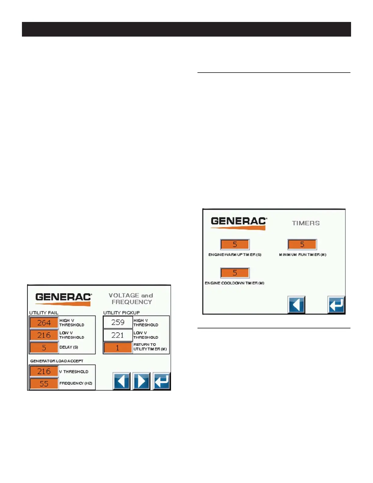
Engine Warm Up Timer - To set this value, press the screen button
that is displaying the current value. Using the pop-up box, enter the
warm up time in seconds. The acceptable range is shown on the
screen. Press Enter to change setting.
Engine Cool Down Timer - To set this value, press the screen
button that is displaying the current value. Using the pop-up box,
enter the engine cool down time in minutes. The acceptable range
is shown on the screen. Press Enter to change setting.
Minimum Run Timer - To set this value, press the screen button
that is displaying the current value. Using the pop-up box, enter the
minimum run time in minutes. The acceptable range is shown on
the screen. Press Enter to change setting.
Figure 14 - Transfer Switch Settings #3
3.10.6 EXERCISE AND CLOCK SETUP
This is the screen to set the system clock and exercise functions
(Figure 15). To return to the System Configuration menu screen
press the return arrow.
System Time and Date - The time is displayed in a 24 hour format.
To set the system clock, press the screen button next to the text.
Using the pop-up box, highlight the setting to be changed with the
left and right arrows. Use the “+” and “-“ buttons to change the
setting. Press enter to update the setting (Figure 17).
Exercise Setup - To setup the exercise function, press the screen
button next to the text. This will bring up the exercise setup screen
on the next screen.
Operation
 Loading...