NOTE
Loosen (Do Not Remove) Terminal Block Screws°
Limit Switch adjustments and securing the Wires
will be done later.
F Lay Wires in channel on top of Rail and secure with Wire Clips
(Figure 14).
G Coil and bundle excess Limit Switch Wires on top of Power
Head with Twist Ties. Leave just enough Wire to reach
Terminals on back of Power Head (Figure 14).
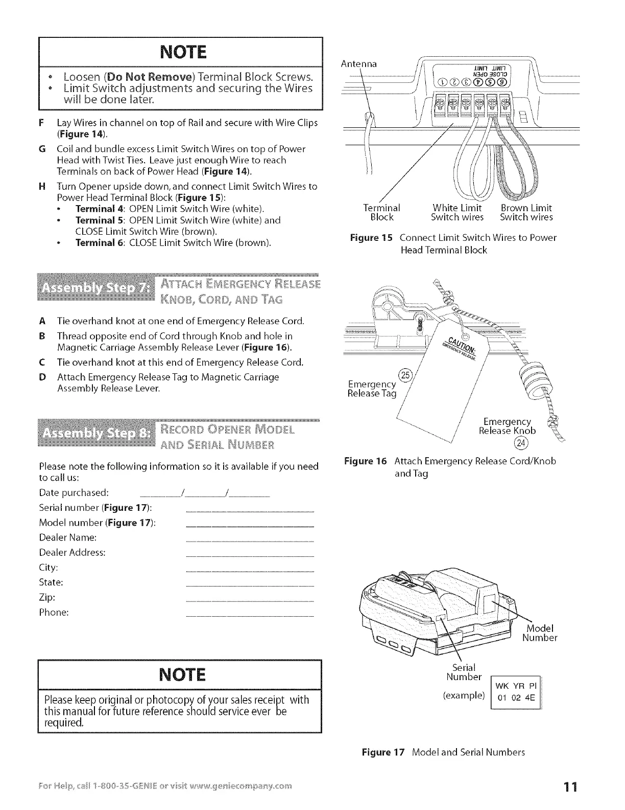
14 Turn Opener upside down, and connect Limit Switch Wires to
Power Head Terminal Block (Figure 15):
* Terminal 4: OPEN Limit Switch Wire (white).
. Terminal 5: OPEN Limit Switch Wire (white) and
CLOSE Limit Switch Wire (brown).
. Terminal 6: CLOSE Limit Switch Wire (brown).
Antenna
J
/
Terminal White Limit Brown Limit
Block Switch wires Switch wires
Figure 15 Connect Limit Switch Wires to Power
Head Terminal Block
_'_ %1C: 11"2 // . '/"
l<&l<l =_ !I W
A Tie overhand knot at one end of Emergency Release Cord.
B Thread opposite end of Cord through Knob and hole in
Magnetic Carriage Assembly Release Lever (Figure 16).
C Tie overhand knot at this end of Emergency Release Cord.
D Attach Emergency ReleaseTag to Magnetic Carriage
Assembly Release Lever.
I:II!COBD I% _i:_, :> _ # '+_#I_:: ,_El @OIsl!L
Al*'_
 Loading...